


Technical Product Manual - DCT1900
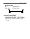
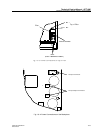
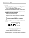
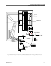
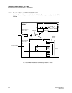
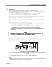
Installation Instructions, Modular Cabinet – Power Cabling
Install-DCT1900/R8/mw 19-7
© 2000-2005
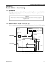
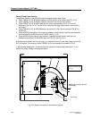
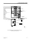
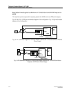
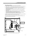
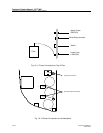
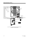
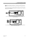
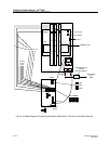
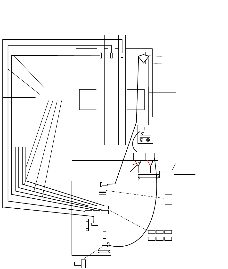
Fig. 19–8 Cable Diagram of Powering the Modular Cabinet and 7 CLUs by an External Source
C
L
U
/
S
L
U
C
L
U
/
S
L
U
C
L
U
/
S
L
U
Back
Plane
A B
MCCB
- +
TSRNB 101 33
To other
CLUs/
SLUs
X112 red
X113 black
PW-EXT
PW-BP
Red
Black
from external
source
(PBX)
TRENB 101 05
-48Vdc
2"
Ferrite Bead to be
installed
during installation
PW1
PW2
PW3
PW5 PW7PW6
PW4
PW2PW3
Ground
Bridge
+
-
PW1
Fuse