


Technical Product Manual - DCT1900
Installation Instructions, Modular Cabinet – Power Cabling
Install-DCT1900/R8/mw 19-9
© 2000-2005
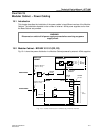
Factory Fitted Power Cabling
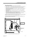
The Modular Cabinet is delivered with the following powering cables fitted:
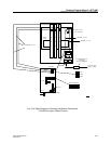
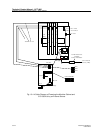
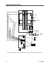
z Cable TRENB 101 02 (190248) between the filter and the lower fuse holders (see Figure 19–
11).
z Cable TRENB 101 04 (#190250) between the switch and the lower two fuse holders.
z Cable between the switch and the upper fuse holders. The end of the cable with piggy-back
faston is connected to the switch.
z Cable between the switch and connector PW–BP on the MCCB. Connects to piggy-back
faston on the switch.
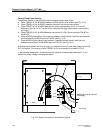
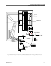
z Cable between the upper fuse holders and connector X112, X113 on the backplane (see
Figure 19–12).
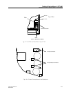
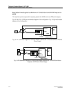
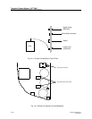
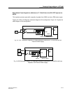
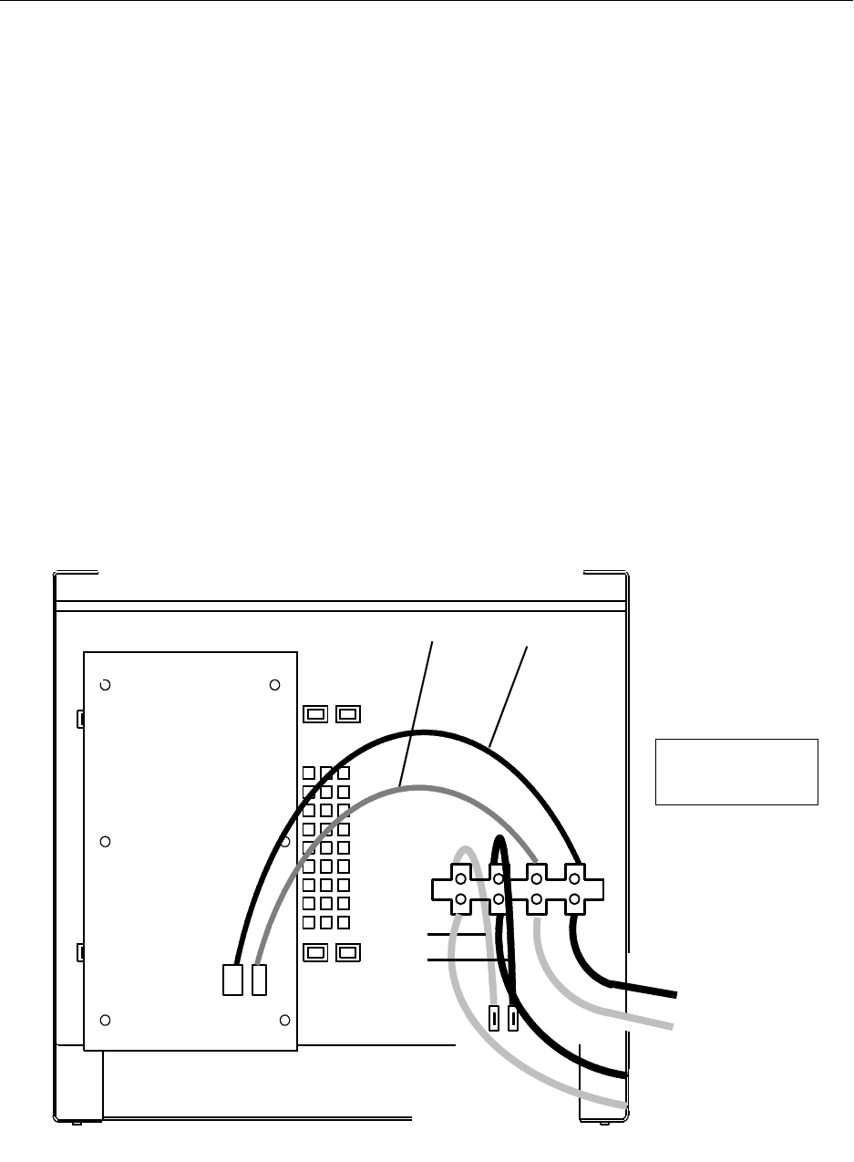
z Cable #190253 (red cable) in two locations: between terminal block A and filter and between
terminal block B and MCCB terminal PW-EXT (see Figure 19-10).
z Cable #190254 (black cable) in two locations: between terminal block A and filter and
between terminal block B and MCCB terminal PW-BP (see Fig. 19-10).
All cables are connected with the red wires (+) connected at the left–hand side except for PW-EXT
connection. The red wire of cable is connected to connector X112(+).
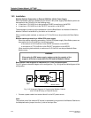
In the following paragraphs it is assumed that the cables are fitted as described above. If you
altered the wiring, change it as described above.
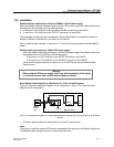
Fig. 19-10 Power Connection to the Modular Cabinet
Red
Black
Botton view
MCCB
+
|
Red
Black
Additional wires to external
-48V supply
L
+
Red
Black
_
B
A
+
_
-48V supply
Warning
Torque the terminal screws
to 7 in./lb.
PW-EXT
Additional wires to
external -48Vdc
-
+
+
-