


Technical Product Manual - DCT1900
Installation Instructions, Base Station – KRC 101 1371
Install-DCT1900/R8/mw 16-1
© 2000-2005
CHAPTER 16
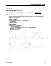
Base Station – KRC 101 1371
**To order a complete Base Station, use Part Number: DB600-001**
16.1 General
The Base Station is connected to the RE by means of minimum CAT3, unshielded twisted pair
cables via a RJ45 connector.
Contents of the Box
The box in which the Base Station is packed contains:
z A Base Station
z Mounting Bracket
Power Distribution
Base Stations can be powered by:
z The RE via the data pairs
z The RE via the data pairs and the EPP pair(s) - for extended distances
z A local AC/-48V DC Adaptor
z An external -48V supply
Note:
For more information about power distribution, refer to Section 4, Chapter 4 "Base Station
Powering".
Firmware
If necessary, the firmware in the Base Station can be updated by downloading the firmware into
the Base Station. Downloading can be performed without disconnecting the Base Stations. The
new firmware is stored in flash memory. How to download the firmware is described in CSMW
Help files.
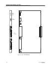
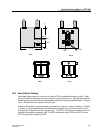
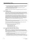
Connectors
X838 : 8–pin RJ45 modular jack
X839 : 8–pin RJ45 modular jack
X840 : 6–pin RJ11 modular jack - for engineering use only
The two RJ45 connectors are interconnected on the board, but only one is connected at a time.
Cabling must be terminated on a modular jack(RJ45).