


Technical Product Manual - DCT1900
Configuration Directions, Base Station Powering
Config-DCT1900/R8/mw 4-3
© 2000-2005
Note:
When using the PBX option refer to the PBX supplier and/or PBX documentation to assure that the
PBX power supply matches the worst case power requirements of the DCT1900 system.
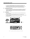
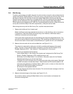
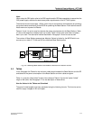
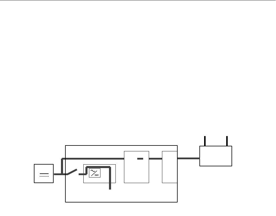
The external source must supply –48Vdc, which may be connected to the backplane for powering
the system boards and directly to the MCCB for powering the Base Stations. Each cabinet uses 50
Watts maximum to power the Boards.
Tables 4-3 and 4-4 can be used to calculate the power requirements for the Base Stations. Table
4-3 has to be used when a battery back–up is used. Table 4-4 has to be used when no battery
back–up is used. The alternative method described in Paragraph 4.5 can be used as well.
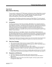
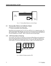
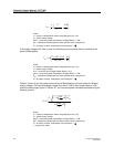
The number of Base Stations powered per Modular Cabinet is limited by the MCCB which can
connect up to a total of 7 CLUs and SLUs to distribute Base Station power.
Fig. 4-3 Powering Base Stations via Modular Cabinet with External Source
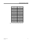
4.4 Tables
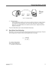
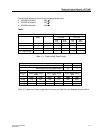
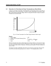
In this Paragraph the Tables for the maximum cable length between the Base Stations and the RE
and tables for the power consumption of the Base Stations and their cables are given.
Table 4–1 gives the "data limited" length of the cable and Table 4–2 gives the "power limited"
length of the cable. See Paragraph 4.1 for the description of these terms.
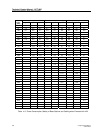
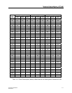
How the Values in the Tables are Calculated
The power limited lengths have been calculated using the following formula. This formula can be
used for supply voltages of 42V and higher.
Base
Station
Backplane
Modular Cabinet
Internal
CLUs
PW-
EXT
External
Source
MCCB