


Technical Product Manual - DCT1900
Maintenance, Test and Maintenance Software
2-2
Maint-DCT1900/R8/mw
© 2000-2005
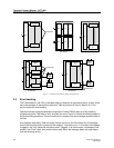
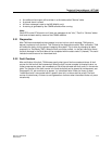
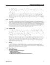
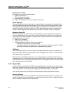
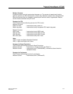
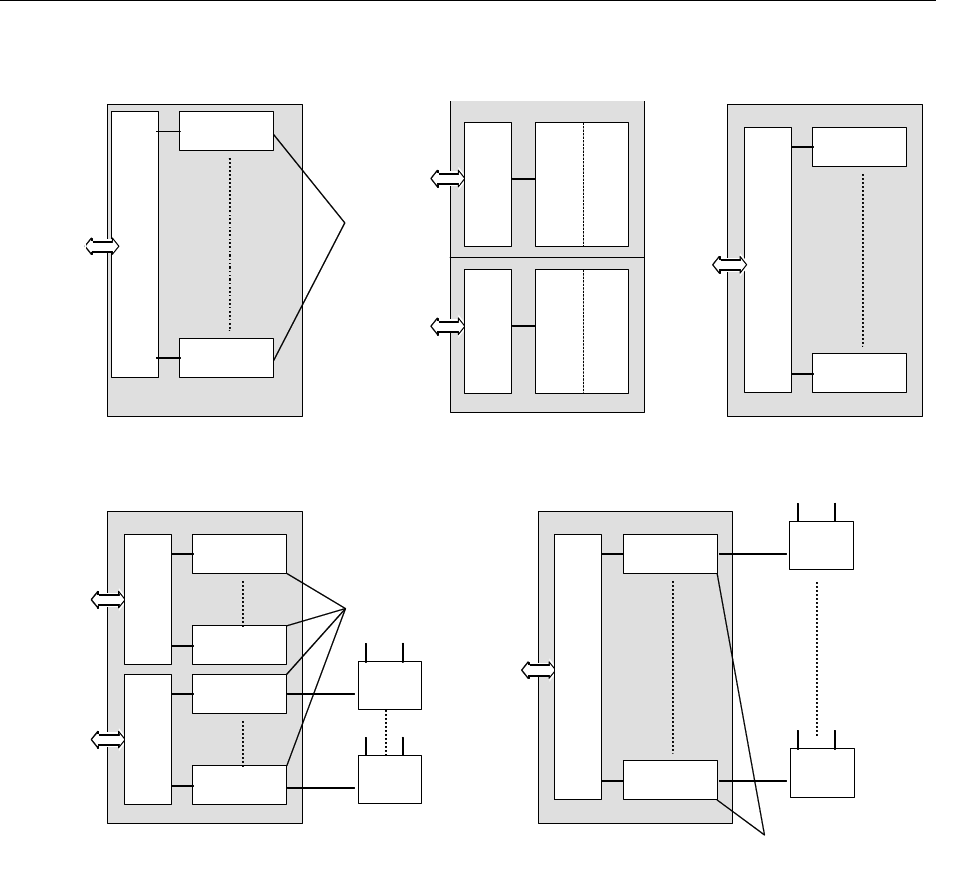
Fig. 2–1 Board Controllers and Peripherals
2.2 Error Handling
The T&M software in the CPU is activated either on detection of operational faults, or when a test
has to be executed. A description of tests that T&M can perform is found in Section 2.3. This
section deals with fault handling.
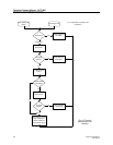
Operational faults and faults detected during tests will cause T&M to start up a fault handling
procedure by which T&M tries to verify and clear the error. Figure 2–2 shows the different steps of
the fault handling procedure. The two conditions for reception of a fault message cause the start of
the flow.
All messages received by T&M are stored in either the Info or the Fault table. Not all messages
that are received are faults. Some are of the category "information only". In this case, the message
is logged in the "Info" table with the status code L (logged). In all other cases, a message will be
written in the "Fault" table, with another status code. When the message deals with a persistent
fault the following occurs:
SPC
P8
SPC
P1
SPU Board
BC
L2
DTC2
DTU Board
L1
L2 L1
DTC1
CLU Board
BC
BC
SPC
8
SPC
1
SLU Board
BC
CLC
8
CLC
1
BC
Base
Station
CLC
8
CLC
1
BC
Base
Station
Base
Station
Base
Station
Peripherals
Peripherals
Peripheral
P8
Peripheral
P1
LTU Board
BC
Peripherals