


Technical Product Manual - DCT1900
Maintenance, Fault Signalling
3-6
Maint-DCT1900/R8/mw
© 2000-2005
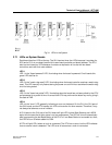
3.7.2 LEDs on CPU
The CPU is the only board having six LEDs. LEDs 1 to 4 are identical to the LEDs on other
boards. LED 5 and 6 are found below the reset button.
LED 5
LED 5 on the CPU board is the "message–received–LED." When a message is written in one of
the info, fault, or service tables, LED 5 is turned on. The LED is cleared immediately after reading
the appropriate error table as it assumes that the reader then takes notice of the message.
LED 6
LED 6 on the CPU is the "T&M–active–LED." This LED turns on when the test and maintenance
module is activated. This is the case when tests are executed, error messages are received or the
error handling procedure is running, see Chapter 2, Paragraph 2.2. As soon as T&M is ready the
LED is off. Because T&M does not run continuously, the LED often blinks.