


Technical Product Manual - DCT1900
Installation Instructions, Modular Cabinet – DLU Cabling
Install-DCT1900/R8/mw 24-1
© 2000-2005
CHAPTER 24
Modular Cabinet – DLU Cabling
24.1 Introduction
This chapter describes the installation of the cabling between the DLU(s) and the PBX. The DLU
cable set, AWS1019, consists of (12) 2 pair cables individually terminated in a RJ11 connector.
Each DLU cable is designed to connect two DLU boards, thus 24 digital extensions, to a single 66
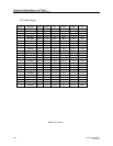
Block. The cable terminates in a 25 pair male AMP connector which mates with a Siemens
66m250 Block or the connector can be cut off and the cables punched down on other types of
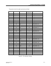
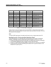
blocks. Refer to Table 24-1 for a pin out of the cable
The Modular Cabinet is provided with a ground strip to connect the cables from the DLUs and the
CLUs to ground. These ground connections are necessary for EMI suppression reasons.
24.2 Installation
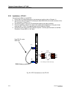
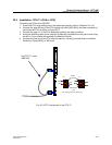
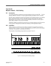
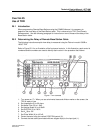
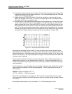
The 24 connectors on the DLU end of the cables are labelled P1 through P24 and should be
installed as shown in Fig. 24-2. Connector 1 goes to the first port of the DLU which is at the bottom
of the board. The male AMP is connected to the 66 Block.
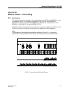
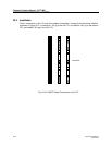
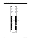
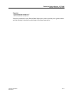
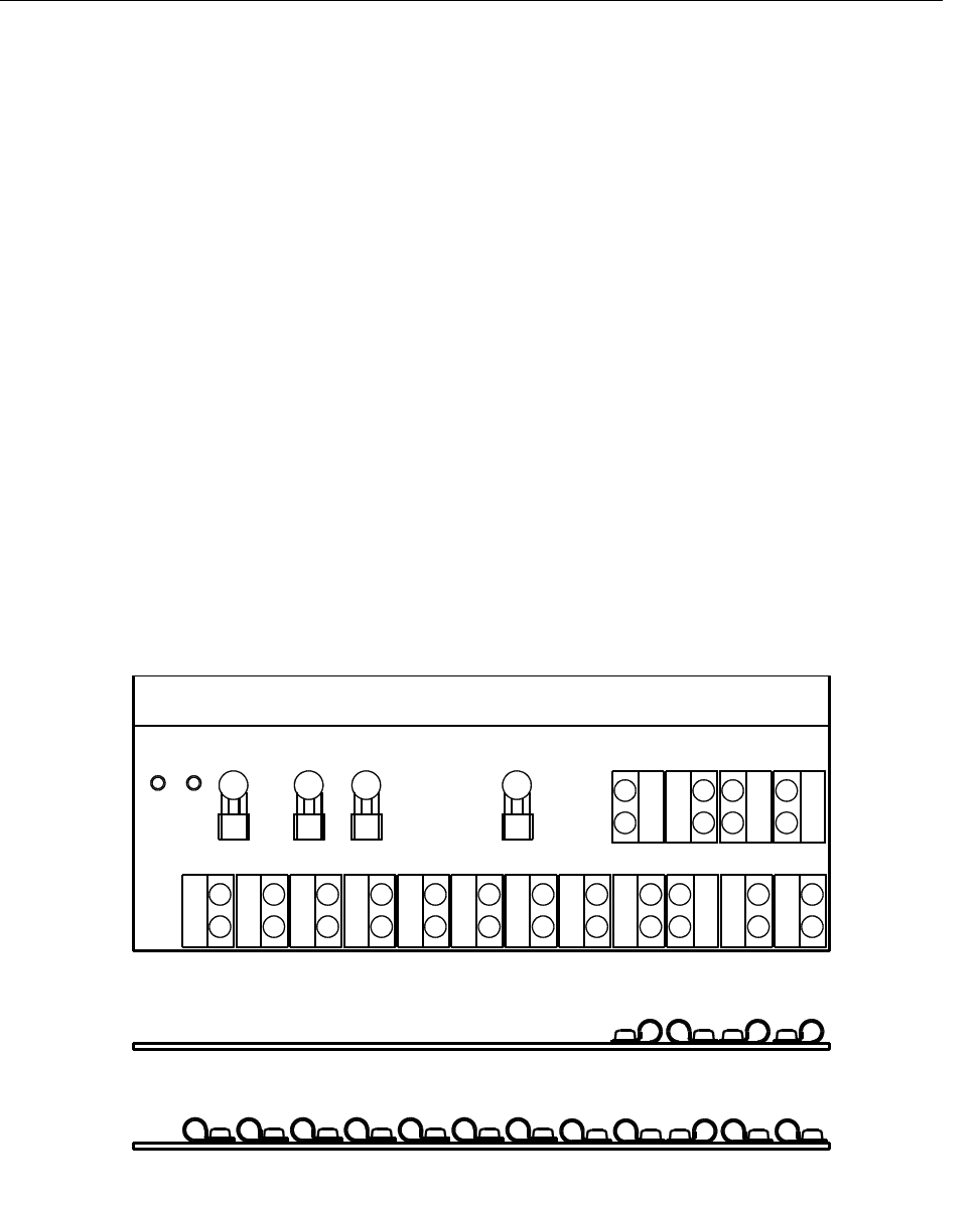
The orientation of the shielding clamps should be as shown in Fig. 24-1.
Fig. 24–1 Ground Strip with Shielding Clamps
Shielding clamps at the front row
Shielding clamp at the back row