


Technical Product Manual - DCT1900
Installation Instructions, Base Station – KRC 101 1371
Install-DCT1900/R8/mw 16-3
© 2000-2005
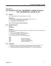
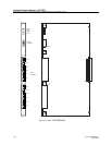
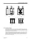
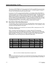
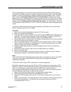
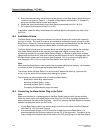
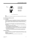
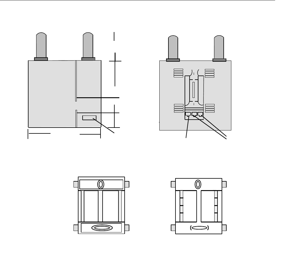
Fig. 16-1 Base Station Cover and Back
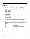
16.2 Base Station Cabling
Each Base Station requires a minimum of 2 pairs of CAT3 unshielded twisted pair cable. These
two pair will be SC0 (signalling channel 0) and SC1 (signalling channel 1). Besides being used for
signalling there is also 48 volts provided between the two pair to power the Base Station. One pair
is at a -48V potential with respect to the other pair.
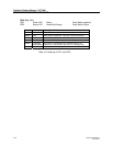
How far a Base Station may be powered on the two pair is shown in a chart in Section 4, Chapter
4, Table 4-3. If the cable distance to the Base Station exceeds the value in the chart for 2 pair,
then the EPP (Express Power Pair) may be used. The EPP is a third pair of wires brought out of
the Radio Exchange that supplies -48V. The EPP contains two wires, EPP0 and EPP1, where
EPP1 is positive with respect to EPP0.
6 5/16"
7 3/16"
RJ45
}
RJ11
label
LED1
LED2
Back Front
Front
Back
3"