


Technical Product Manual - DCT1900
Installation Instructions, Modular Cabinet – CLU/SLU to Base Station Cabling
Install-DCT1900/R8/mw 21-3
© 2000-2005
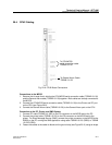
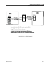
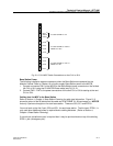
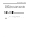
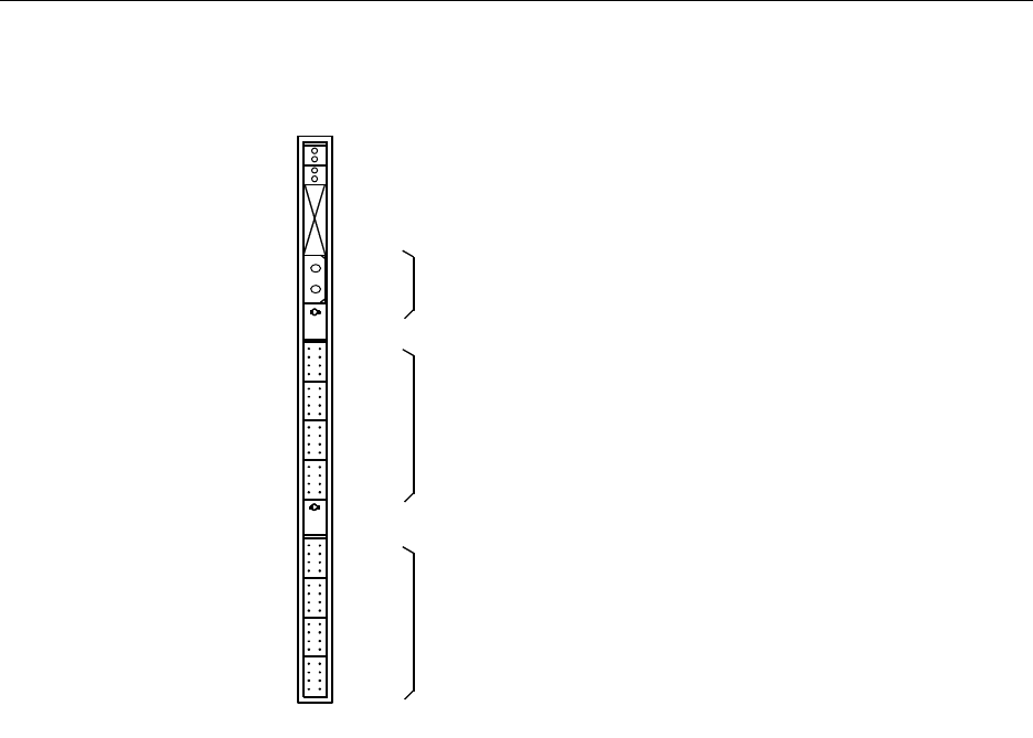
Fig. 21–2 CLU/MDF Cable Connections on the CLU or SLU
Base Station Power
The following installation steps are necessary when the Base Stations are powered via the
Modular Cabinet. Refer to Chapter 19 on how to supply Base Station power to the MCCB.
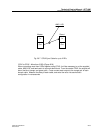
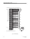
1. Connect connectors PW1 on the MCCB to the Base Station power connectors on the furthest
left CLU or SLU using the CLU/MCCB Power cable (see Fig. 21–2).
2. Connect PW2 – PW7 to the power connections of the other CLU or SLUs starting at the next
CLU or SLU.
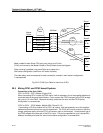
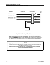
Cabling from the MDF to the Base Station
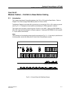
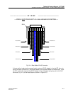
Refer to Section 4, Chapter 4, Base Station Powering for cable type information. Figure 21-3
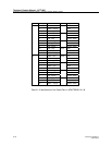
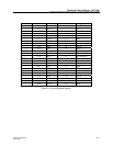
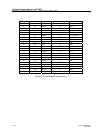
shows the pinout of the 66 blocks that the cable set NTM/TSRNB 101 29 terminates on. NOTICE
that only 3 pairs are brought out for each base station. These are SC0, SC1 and EPP0/1.
You must hook up the first 2 pair, SC0 and SC1, for each base station. The third pair, EPP0/1, is
only used when additional power is required due to cabling distances. (Refer to Section 4,
Chapter 4, Base Station Powering).
If a fourth pair (white/brown pair) is required then it may be punched down on top of the existing
EPP0/1, pair (white/green pair).
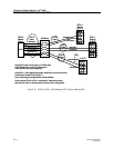
CLC1
CLC2
CLC3
CLC4
CLC5
CLC6
CLC7
CLC8
To cable TSRNB 101 29/2 or
TSRNB 101 46/2
To cable TSRNB 101 29/1 or
TSRNB 101 46/1
Base
Station
Power
To cable TSRNB 101 33