


Technical Product Manual - DCT1900
Maintenance, Test and Maintenance Software
2-8
Maint-DCT1900/R8/mw
© 2000-2005
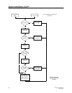
Board Power–on Reset
A board power–on reset is generated when:
z System is switched on.
z CPU reset button is pressed.
z Board inserted in the system.
As a result, the board power–on test is started on the board.
Watch–dog Reset
There are two different watch–dog resets: an expected and an unexpected. An expected watch–
dog reset happens during the watch–dog test, which is the final test of the board power–on test.
An unexpected watch–dog reset happens during normal operation when the CPU or the board
controller is reset by their watch–dog circuit. A CPU watch–dog reset results in a restart of the
system. A watch–dog reset from a board controller results in a power–on test for that board.
Backplane Reset (SW)
When the last board of a specific kind is not responding any more, the system cannot work or a
minimum configuration error occurs. When one of the elementary functions is not available any
more, the CPU will force the system to restart (power on test) to check what is wrong. Minimum
configuration errors occur when:
z Last SPU-S is removed.
z Last DTU/LTU is removed.
z Last Base Station is removed. This can be caused by:
- The last CLU and the last SLU are removed.
- The last Base Station of the last CLU or SLU is removed, while still having CLUs or SLUs
connected (connection of Base Stations is detected by the system).
T&M Reset
When T&M detects an error, it sends a reset to the appropriate board controller or peripheral to
start up a local test. When the fault persists, an error message will be written in the service table
and a general alarm is generated.
When the fault is intermittent, there will be no error signalling to the outside world, but the error
message remains in the Fault table and the absolute and relative reset counters are incremented.
When the reset counter exceeds its threshold level, an error message is written in the service table
and a subsequent alarm is generated.
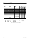
2.4.2 Reset Table
In order to keep a reset–history, the CPU has a reset table where all resets are counted for each
board. Also, resets to the various circuits on the CPU board are counted. The value of the counter
in the reset table can be viewed by selecting System-Show Reset History in the CSMW.
Two counter types exist for counting these resets: absolute counters and relative counters.
Absolute Counters
An absolute counter counts all resets since the associated board was placed in the system. This
counter is cleared only at re–initialization or when the board is pulled out with a Replace/Remove
action. Absolute counters have no threshold level.