


Technical Product Manual - DCT1900
Installation Instructions, Modular Cabinet – DTU Cabling
22-2
Install-DCT1900/R8/mw
© 2000-2005
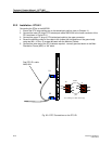
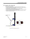
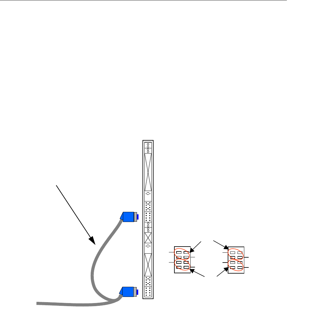
22.2 Installation - DTU-E1
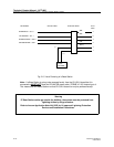
Connecting the DTUs to the MS/PBX
1. Ensure the DTU strap settings are in the twisted pair position (refer to Chapter 11).
2. Connect the lower X2 plug of DTU twisted pair cable AWS1034 to the lower connector of the
DTU as shown in Figure 22–2.
3. Connect the upper X1 plug of DTU twisted pair cable to the upper connector.
4. Screw the shielding clamp of the cable to the furthest left free position on the ground strip
using two M3 x 10 torx 10 screws delivered with the Modular Cabinet.
5. Connect the other end of the DTU cable as required - normally punched down on the Main
Distribution Frame (MDF) or “66” block.
Fig. 22–2 DTC Connections on the DTU-E1
Dual DTU E1 cable
AWS1034
X1
WHT
WHTWHT
BRN
GRN
12
78
WHT
WHT
ORN
BLU
12
78
WHT
WHTWHT
ORN
BLU
12
78
X2
X1
RCV
pairs
XMIT
pairs
View looking into DTU board edge
X2