


Technical Product Manual - DCT1900
Configuration Directions, Base Station Powering
4-2
Config-DCT1900/R8/mw
© 2000-2005
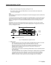
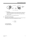
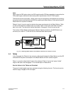
Fig. 4–1 Powering Base Stations by a remote Supply
4.3 Powering Base Stations via the Modular Cabinet
Base Stations are powered via the following path:
z External source-MCCB-CLU/SLU-Base Station
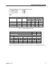
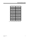
Base Stations are connected to the CLU or SLU via an MDF by 2, 3 or 4 twisted pair cables. The
maximum permissible length depends on the wire size and the number of pairs used between the
MDF and Base Station. The CLU/MDF cable contains only one Express Powering Pair (EPP), but
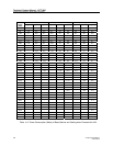
this may be doubled up on the MDF. Table 4–2 shows the maximum cable lengths.
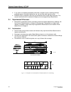
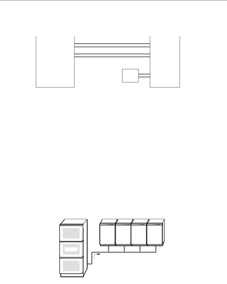
4.3.1 –48V External Source Powering
Via an external -48V source, any configuration of cabinets and Base Stations can be powered as
long as the power specifications of the external source are met. This method is suitable for any
situation where PBX power is available (see Figure 4–2) or any other -48V supply with sufficient
current capacity. The maximum cable lengths are given in Table 4–2 (42V and 48V column).
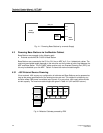
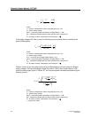
Fig. 4-2 Modular Cabinets powered by PBX
Local
Power
Radio
Exchange
Base
Station
SC0
SC1
EPP
data pair
data pair
PBX
CAB
4
CAB
3
CAB
1
CAB
2