


Technical Product Manual - DCT1900
Installation Instructions, Line Termination Unit (LTU) – REX-BRD0007 or ROFNB 157 02/6 and LTU2 - REX-BRD0019A or ROFNB
Install-DCT1900/R8/mw 14-1
© 2000-2005
CHAPTER 14
Line Termination Unit (LTU) – REX-BRD0007 or ROFNB 157 02/6 and
LTU2 - REX-BRD0019A or ROFNB 157 25/2
14.1 General
The LTU supports 8 two wire analog connections to a PBX.
Maintenance
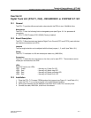
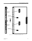
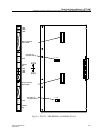
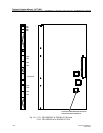
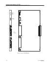
The LTU contains the following field–exchangeable part (see Figure 14-1):
z LTU Firmware - REX-SW0012 or RYS 105 661
z LTU2 Firmware - REX-LTU2FW 01/1H
Note: LTU2 can only be used with CPU2 board.
14.2 Board Description
Jumpers
Not applicable.
Connectors
The LTU has 4 connectors at the front by which Line Termination Circuits (LTCs) are connected to
the PBX/Centrex.
1. LTC1 – LTC4: connection of PBX line 1 to 4
2. LTU Ground: connection of signalling earth (ELR)
3. LTC5 – LTC8: connection of PBX line 5 to 8
4. Pin a is tip, pin b is ring. Pins a’ and b’ are not used.
LEDs
LED1 : Normally on. Power On
LED2 : Normally off. Watch–dog
LED3 : Normally off. Board not polled
LED4 : Normally off. Board Error
14.3 Installation
1. Insert the LTU gently into the card guide in its specified board position (See Figure 14-1).
2. Gently push the board into the back connector until it locks. Do not use any force.
3. Connect the connectors from cable set NTM/TSRNB 101 31 to the front of the board.