


Technical Product Manual - DCT1900
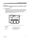
Installation Instructions, Modular Cabinet Connection Board (MCCB) - ROANB 101 28
17-4
Install-DCT1900/R8/mw
© 2000-2005
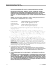
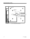
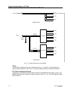
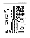
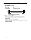
Connectors
Ground bridge : For connecting the plus pole of PW–EXT to ground.
DTC1, DTC2, DTC3, DTC4, : For connection of 6 coaxial DTU-E1 cables (PBX/MCCCB
DTC5, DTC6 (DTC–OUT) cables) to the PBX.
DTC1, DTC2, DTC3, DTC4, : For connection of 6 coaxial DTU-E1 cables (DTU/MCCB
DTC5, DTC6 (DTC–IN) cables) to the DTU.
GA–IN : For connection of the General Alarm input (General Alarm
cable) from the CPU board.
GA–OUT : General Alarm output to alarm device.
LTU1, LTU2, LTU3, LTU4, : For signalling ground cables (LTU/MCCB ground cable) to 7
LTU5, LTU6, LTU7 LTUs.
PBX : For the signalling ground connection to the PBX. This
connection is only used when earth signalling is used.
PC : For connection to PC (PC Cable).
PR : For connection to printer (printer cable).
PW–BP : For the power connection to the backplane (MCCB power
cable, for Base Station powering).
PW1, PW2, PW3 : For power cable to 3 CLUs/SLUs (CLU/MCCB power cable)
(backplane power) when using the backplane power.
PW–EXT: : For optional external power supply (for Base Station powering).
PW1, PW2, PW3, PW4, PW5, : For power cable to 7 CLUs/SLUs (CLU/MCCB power cable)
PW6, PW7 (external power) when using external power.
RS232 : For cable to CPU for PC and printer (RS232 to MCCB cable).
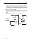
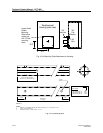
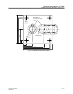
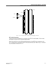
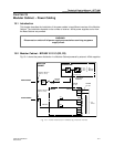
17.2 Installation
The Modular Cabinet is delivered with the MCCB mounted. The cables to the CPU are already
connected to the MCCB. For installation of these cables and the installation of the other cables
refer to the relevant chapters.