


Chapter 3 Configuring the Cisco IP Phone Models 7905G and 7912G for SIP
Basic Configuration Steps in a TFTP Server Environment
3-6
Cisco IP Phone Models 7905G and 7912G Administrator Guide (SIP)
OL-4277-01
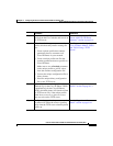
Therefore, the resulting value of the OpFlags parameter becomes the following
bitmap representation:
0000 0000 0000 0000 0000 0000 0101 0010
In hexadecimal format, this value is 0x00000052.
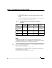
Step 2 Set bits 18-29 of the VLANSetting parameter to voice VLAN ID 115. This setting
translates to the following bitmap
xx00 0001 1100 11xx xxxx xxxx xxxx xxxx
where 000001110011 is the binary representation of the decimal value 115.
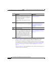
The remaining bits of the VLANSetting parameter, using all default values, make
up the following representation:
00xx xxxx xxxx xx00 0000 0000 0010 1011
Therefore, the resulting value of the VLANSetting parameter becomes the
following bitmap representation:
0000 0001 1100 1100 0000 0000 0010 1011
In hexadecimal format, this value is 0x01cc002b.
Related Topics
• Default Boot Load Behavior, page 3-2
• Basic Configuration Steps in a TFTP Server Environment, page 3-6
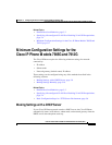
• Minimum Configuration Settings for the Cisco IP Phone Models 7905G and
7912G, page 3-9
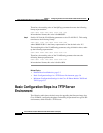
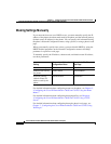
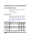
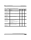
Basic Configuration Steps in a TFTP Server
Environment
The following table shows the basic steps for upgrading the firmware image for a
Cisco IP Phone, configuring the phone, and making it operational in a typical SIP
environment, which includes a TFTP server.