


C-9
Cisco IP Phone Models 7905G and 7912G Administrator Guide (SIP)
OL-4277-01
Appendix C SIP Call Flows
Call Flow Scenarios for Successful Calls
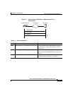
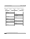
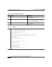
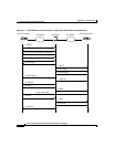
Table C-5 Action Descriptions
Step Action Description
Step 1
INVITE—Cisco IP Phone A to SIP server Cisco IP Phone A sends a call session
INVITE request to the SIP server to pass on to
Cisco IP Phone B.
Step 2
100 Trying—SIP server to Cisco IP Phone A SIP server returns a 100 trying message,
indicating that the INVITE request has been
received.
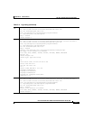
Step 3
INVITE—SIP server to Cisco IP Phone B SIP server sends the call session INVITE
request to Cisco IP Phone B.
Step 4
100 Trying—Cisco IP Phone B to SIP server Cisco IP Phone B returns a 100 trying
message indicating that the INVITE request
has been received.
Step 5
180 Ringing—Cisco IP Phone B to SIP
server
Cisco IP Phone B sends a 180 ringing
response to the SIP server to pass on to
Cisco IP Phone A.
Step 6
180 Ringing—SIP server to Cisco IP Phone
A
SIP server sends the 180 ringing response to
Cisco IP Phone A.
Step 7
200 OK—Cisco IP Phone B to SIP server Cisco IP Phone B sends a 200 OK message to
the SIP server indicating that a connection has
been established.
Step 8
200 OK—SIP server to Cisco IP Phone A SIP server passes the 200 OK message to
Cisco IP Phone A.
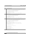
Step 9
ACK—Cisco IP Phone A to SIP server Cisco IP Phone A sends acknowledgement of
the 200 OK response to the SIP server to pass
on to Cisco IP Phone B.
Step 10
ACK—SIP server to Cisco IP Phone B SIP server passes ACK response to
Cisco IP Phone B.
A two-way voice path is established between Cisco IP Phone A and Cisco IP Phone B.
Step 11
BYE—Cisco IP Phone A to SIP server Cisco IP Phone A terminates the call session
and sends a BYE request to the SIP server
indicating that Cisco IP Phone A wants to
terminate the call.