


Chapter 2 Installing the Cisco IP Phone Models 7905G and 7912G
Installing the Cisco IP Phone Models 7905G and 7912G
2-8
Cisco IP Phone Models 7905G and 7912G Administrator Guide (SIP)
OL-4277-01
Warning
To avoid electric shock, do not connect safety extra-low voltage (SELV) circuits
to telephone-network voltage (TNV) circuits. LAN ports contain SELV circuits,
and WAN ports contain TNV circuits. Some LAN and WAN ports both use RJ-45
connectors. Use caution when connecting cables. To see translations of the
warnings that appear in this publication, refer to the Regulatory Compliance
and Safety Information document that accompanied this device.
Caution Do not cover or block the air vents on the back side of the Cisco IP Phone.
Overheating can cause permanent damage to the unit.
Caution If you plan to power your phone locally (instead of receiving power through the
Ethernet connection), use only a Cisco 48 volt power supply designed to work
with a Cisco IP Phone.
Note Do not use hooded cables with the Cisco IP Phone models 7905G and 7912G
because they can cause the phone to rock.
Procedure
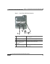
Step 1 Use a Category 3 or 5 straight-through Ethernet cable to connect the 10BASET
port on the Cisco IP Phone 7905G or the 10/100 SW port on the Cisco IP Phone
7912G to an Ethernet port.
Step 2 Connect the handset to the handset port.
Ensure that the end of the cord with the longer uncoiled section is connected to
the body of the phone.
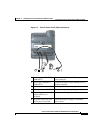
Step 3 Connect a Category 3 or 5 Ethernet cable to the 10/100 PC port on the back of the
Cisco IP Phone 7912G (optional).
Use a crossover Ethernet cable to connect from the access port to another Ethernet
device (such as a router or desktop computer) without using a hub. Otherwise, use
a straight-through Ethernet cable.
The Cisco IP Phone 7905G does not have a 10/100 PC port.