


PicoBlaze 8-bit Embedded Microcontroller www.xilinx.com 91
UG129 (v1.1.2) June 24, 2008
R
Appendix C
PicoBlaze Instruction Set and Event
Reference
This appendix provides a detailed operational description of each PicoBlaze™ processor
instruction and the Interrupt and Reset events, including pseudocode for each instruction.
The pseudocode assumes that all variable to the right of an assignment symbol (
Å) have
the original value before the instruction is executed. The values for variables to the left of
an assignment symbol are assigned at the end of the instruction and all assignments occur
in parallel, similar to VHDL.
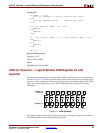
ADD sX, Operand —Add Operand to Register sX
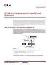
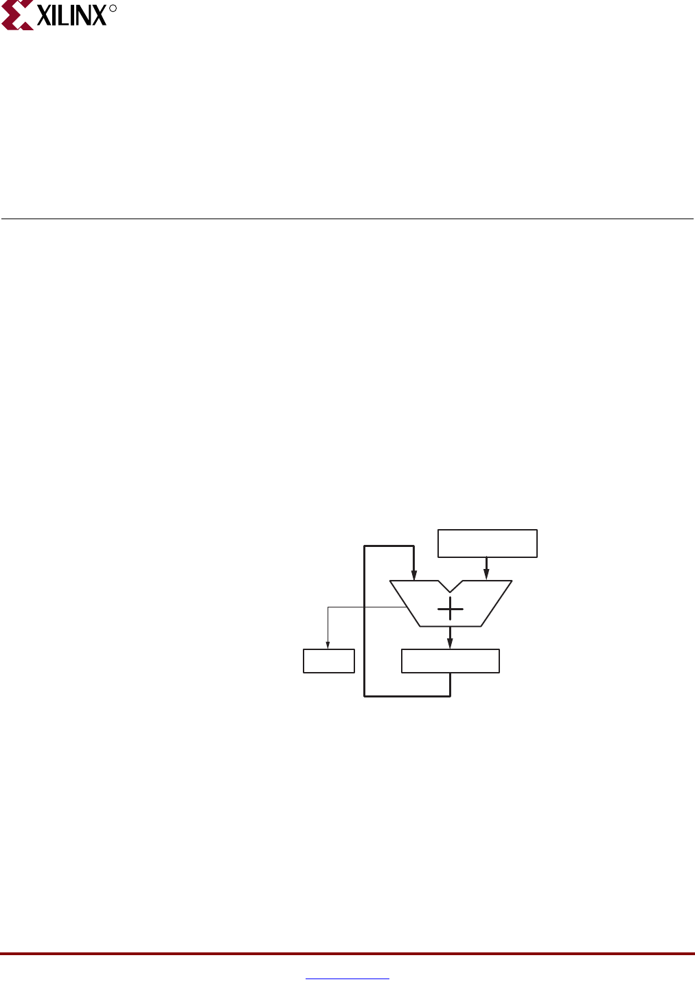
The ADD instruction performs an 8-bit addition of two operands, as shown in Figure C-1.
The first operand is any register, which also receives the result of the operation. A second
operand is also any register or an 8-bit constant value. The ADD instruction does not use the
CARRY as an input, and hence, there is no need to condition the flags before use. Flags are
affected by this operation.
Example
Operand is a register location, sY, or an immediate byte-wide constant, kk.
ADD sX, sY; Add register. sX = sX + sY.
ADD sX, kk; Add immediate. sX = sX + kk.
Description
Operand is added to register sX. The ZERO and CARRY flags are set appropriately.
Figure C-1: ADD Operation
Register sX
Register sY or
Literal kk
CARRY
Carry Out
UG129_aC_01_051604