


PicoBlaze 8-bit Embedded Microcontroller www.xilinx.com 109
UG129 (v1.1.2) June 24, 2008
SL[ 0 | 1 | X | A ] sX — Shift Left Register sX
R
Example
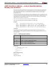
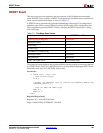
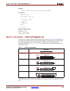
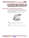
RR sX; Rotate right. Bit sX[0] copied into CARRY
Pseudocode
CARRY Å sX[0]
sX Å {sX[0], sX[7:1]}
if ( sX = 0 ) then
ZERO Å 1
else
ZERO Å 0
endif
PC Å PC + 1
Registers/Flags Altered
Registers: sX, PC
Flags: CARRY, ZERO
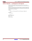
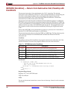
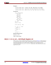
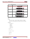
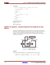
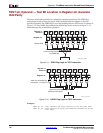
SL[ 0 | 1 | X | A ] sX — Shift Left Register sX
There are four variants of the shift left instruction, as shown in Table C-7, that operate on
any single data register. Each bit in the specified register is shifted left by one bit position.
The most-significant bit, bit 7, shifts into the CARRY bit. The last character of the
instruction mnemonic—i.e., ‘0’, ‘1’, ‘X’, or ‘A’—indicates the value shifted into the least-
significant bit, bit 7.
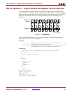
The ZERO flag is always 0 after executing the SL1 instruction because register sX is never
zero.
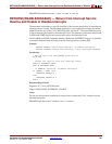
Table C-7: Shift Left Operations
Shift Left
SL0 sX Shift Left with ‘0’ fill.
SL1 sX Shift Left with ‘1’ fill.
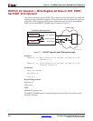
SLX sX Shift Left, eXtend bit 0.
SLA sX Shift Left through All bits, including CARRY.
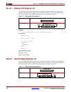
7 6 5 4 3 2 1 0
Register sXCARRY
‘0’
7 6 5 4 3 2 1 0
Register sXCARRY
‘1’
7 6 5 4 3 2 1 0
Register sXCARRY
7 6 5 4 3 2 1 0
Register sXCARRY