


PicoBlaze 8-bit Embedded Microcontroller www.xilinx.com 41
UG129 (v1.1.2) June 24, 2008
R
Chapter 4
Interrupts
The PicoBlaze™ processor provides a single interrupt input signal. If the application
requires multiple interrupt signals, combine the signals using simple FPGA logic to form a
single INTERRUPT input signal. After reset, the INTERRUPT input is disabled and must
be enabled via the ENABLE INTERRUPT instruction. To disable interrupts at any point in
the program, issue a DISABLE INTERRUPT instruction.
Once enabled, the INTERRUPT input signal must be applied for at least two clock cycles to
guarantee that it is recognized, generating an INTERRUPT Event.
An active interrupt forces the PicoBlaze processor to immediately execute the CALL 3FF
instruction immediately after completing the instruction currently executing. The CALL
3FF instruction is a subroutine call to the last program memory location. The instruction in
the last location defines how the application code should handle the interrupt. Typically,
the instruction at location 3FF is a jump location to an interrupt service routine (ISR).
The PicoBlaze microcontroller automatically performs other functions. The interrupt
process preserves the current ZERO and CARRY flag contents and disables any further
interrupts. Likewise, the current program counter (PC) value is pushed onto the
CALL/RETURN stack. Interrupts must remain disabled throughout the interrupt
handling process.
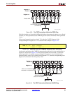
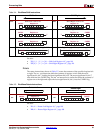
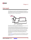
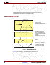
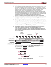
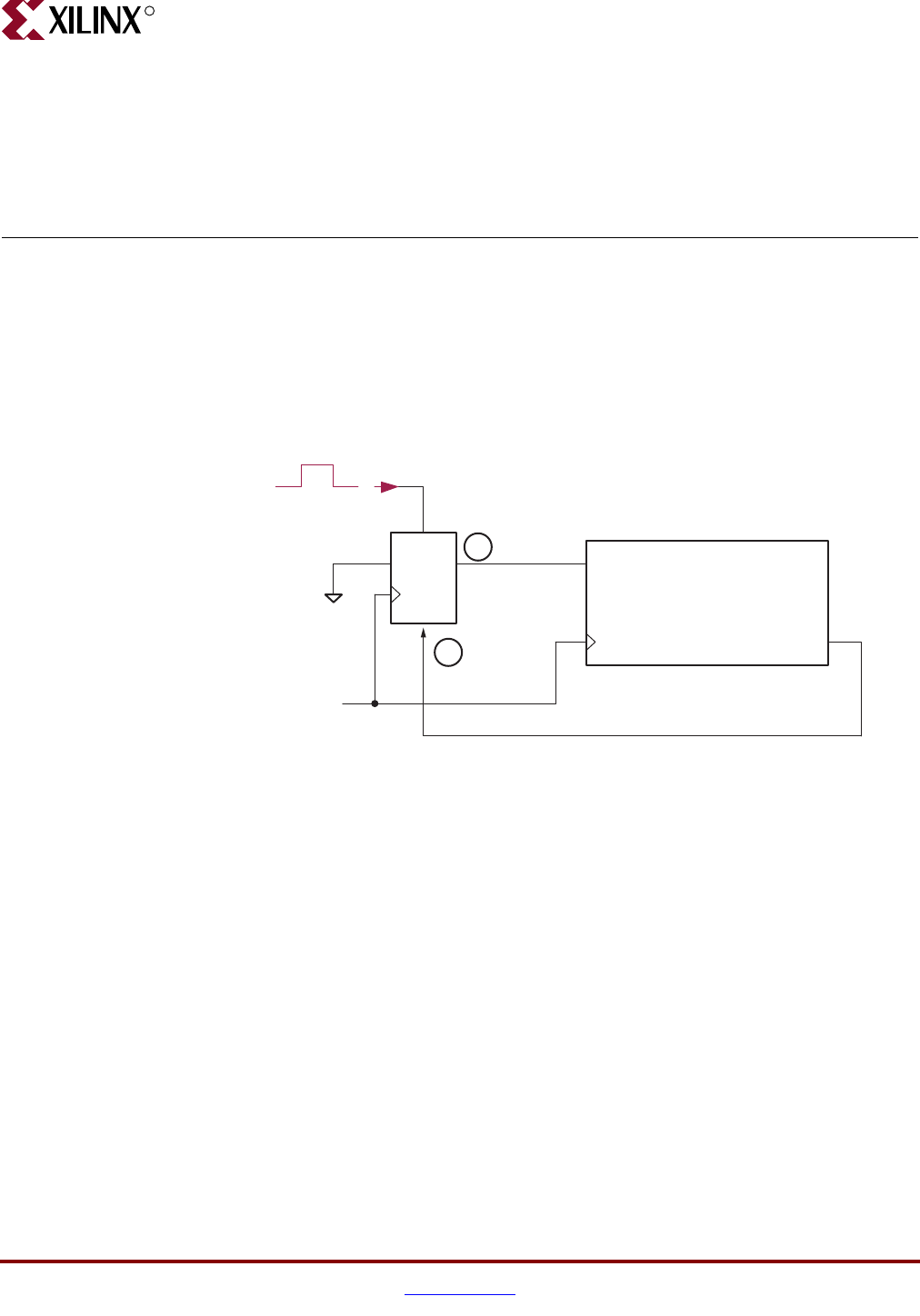
As shown in Figure 4-3, the PicoBlaze microcontroller asserts its INTERRUPT_ACK signal
during the second cycle of the two-cycle Interrupt Event to indicate that the interrupt was
recognized. The INTERRUPT_ACK signal may be used to clear external interrupts, as
shown in Figure 4-1.
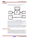
Figure 4-1: Simple Interrupt Logic
DQ
SET
RST
Interrupt signal
INTERRUPT
INTERRUPT_ACK
PicoBlaze Microcontroller
2
3
UG129_c4_01_060404