


PicoBlaze 8-bit Embedded Microcontroller www.xilinx.com 73
UG129 (v1.1.2) June 24, 2008
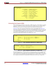
Black Box Instantiation of KCPSM3 using KCPSM3.ngc
R
Black Box Instantiation of KCPSM3 using KCPSM3.ngc
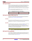
The Xilinx NGC file included with the reference design was generated by synthesizing the
KCPSM3.vhd file using the Xilinx Synthesis Tool (XST), without inserting I/O buffers.
When used as a “black box” in a Spartan-3, Virtex-II or Virtex-II Pro FPGA design, the
PicoBlaze microcontroller is merged with the remainder of the FPGA design during the
translate phase (ngdbuild).
Note that buses are defined in the style IN_PORT<7:0> with individual signals defined as
in_port_0 through in_port_7.
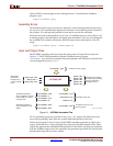
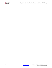
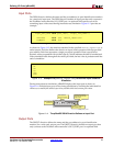
Generating the Program ROM using prog_rom.coe
The KCPSM assembler generates a memory coefficients file (*.coe). Using the Xilinx
CORE Generator™ system, create a block ROM using the *.coe file.
The file defines the initial contents of a block ROM. The output files created by the CORE
Generator system can then be used in the normal design flow and connected to the
PicoBlaze “black box” instantiation of the KCPSM3 module.
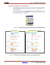
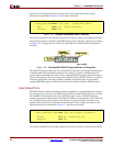
Generating an ESC Schematic Symbol
To generate an ESC schematic symbol, use the embedded_KCPSM3.vhd file.
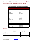
Verilog Design Flow
Beginning with XST/ISE 6.2i, the Xilinx development software allows mixed-language
design projects using both VHDL and Verilog. Consequently, the KCPSM3 VHDL source
can be included within a Verilog project. The KCPSM3 assembler generates a Verilog file
named <filename>.v that defines the initial contents (see assembler notes for more
detail). This Verilog file is used to implement and simulate the PicoBlaze instruction store.
The details of mixed VHDL and Verilog language support in the Xilinx ISE software is
described in detail in Chapter 8, “Mixed Language Support”, in the XST User Guide.
• XST User Guide
http://toolbox.xilinx.com/docsan/xilinx10/books/docs/xst/xst.pdf
Black-box instantiation is an alternative Verilog design approach. Instantiate the
kcspm3.ngc black box file within the Verilog design to define the remainder of the
processor.