


116 www.xilinx.com PicoBlaze 8-bit Embedded Microcontroller
UG129 (v1.1.2) June 24, 2008
Appendix : PicoBlaze Instruction Set and Event Reference
R
TEST sX, Operand — Test Bit Location in Register sX, Generate
Odd Parity
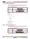
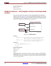
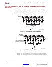
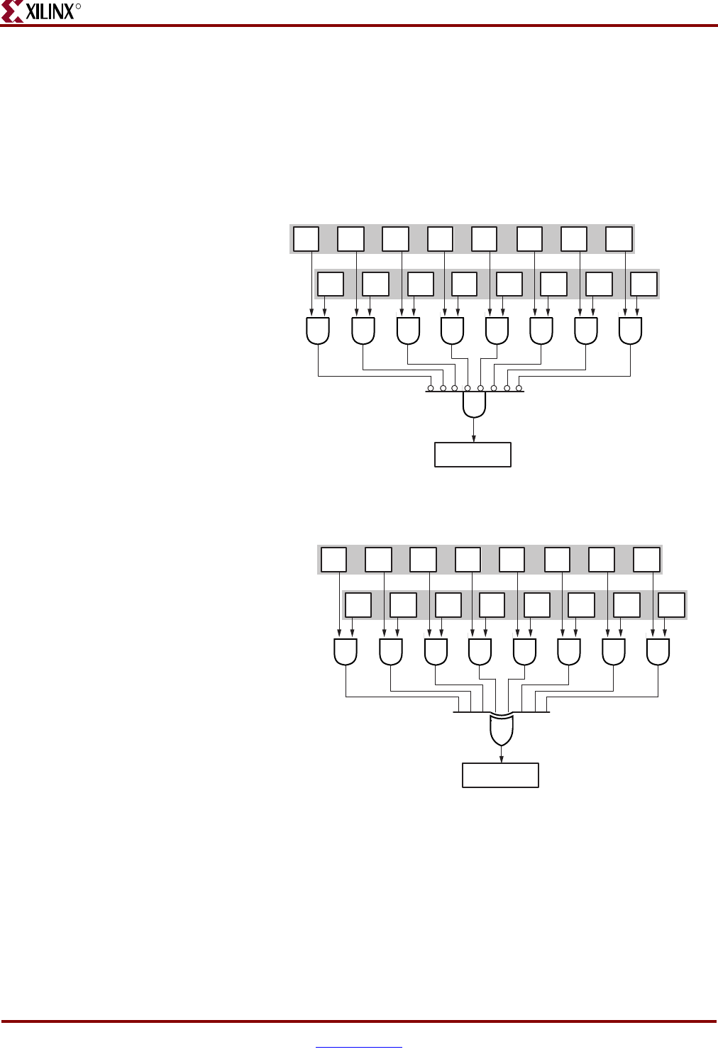
The TEST instruction performs two related but separate operations. The ZERO flag
indicates the result of a bitwise logical AND operation between register sX and the
specified Operand. The ZERO flag is set if the resulting bitwise AND is zero, as shown in
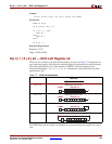
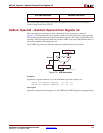
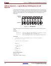
Figure C-11. The CARRY flag indicates the XOR of the result, as shown in Figure C-12,
which behaves like an odd parity generator.
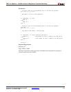
Examples
TEST sX, sY ; Test register sX using register sY as the test mask
TEST sX, kk ; Test register sX using the immediate constant kk as the
; test mask
Figure C-11: ZERO Flag Logic for TEST Instruction
Figure C-12: CARRY Flag Logic for TEST Instruction
7 6 5 4 3 2 1 0
7 6 5 4 3 2 1 0Register sX
Register sY
Literal kk
Bitwise AND
ZERO
If all bit results are zero,
set ZERO flag.
UG129_c3_03_051404
7 6 5 4 3 2 1 0
7 6 5 4 3 2 1 0Register sX
Register sY
Literal kk
CARRY
UG129_c3_04_051404
Mask out unwanted bits.
0=mask bit, 1=include bit
Generate odd parity
(XOR) from bit results.