


50 www.xilinx.com PicoBlaze 8-bit Embedded Microcontroller
UG129 (v1.1.2) June 24, 2008
Chapter 6: Input and Output Ports
R
INPUT Operations
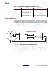
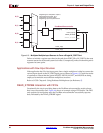
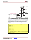
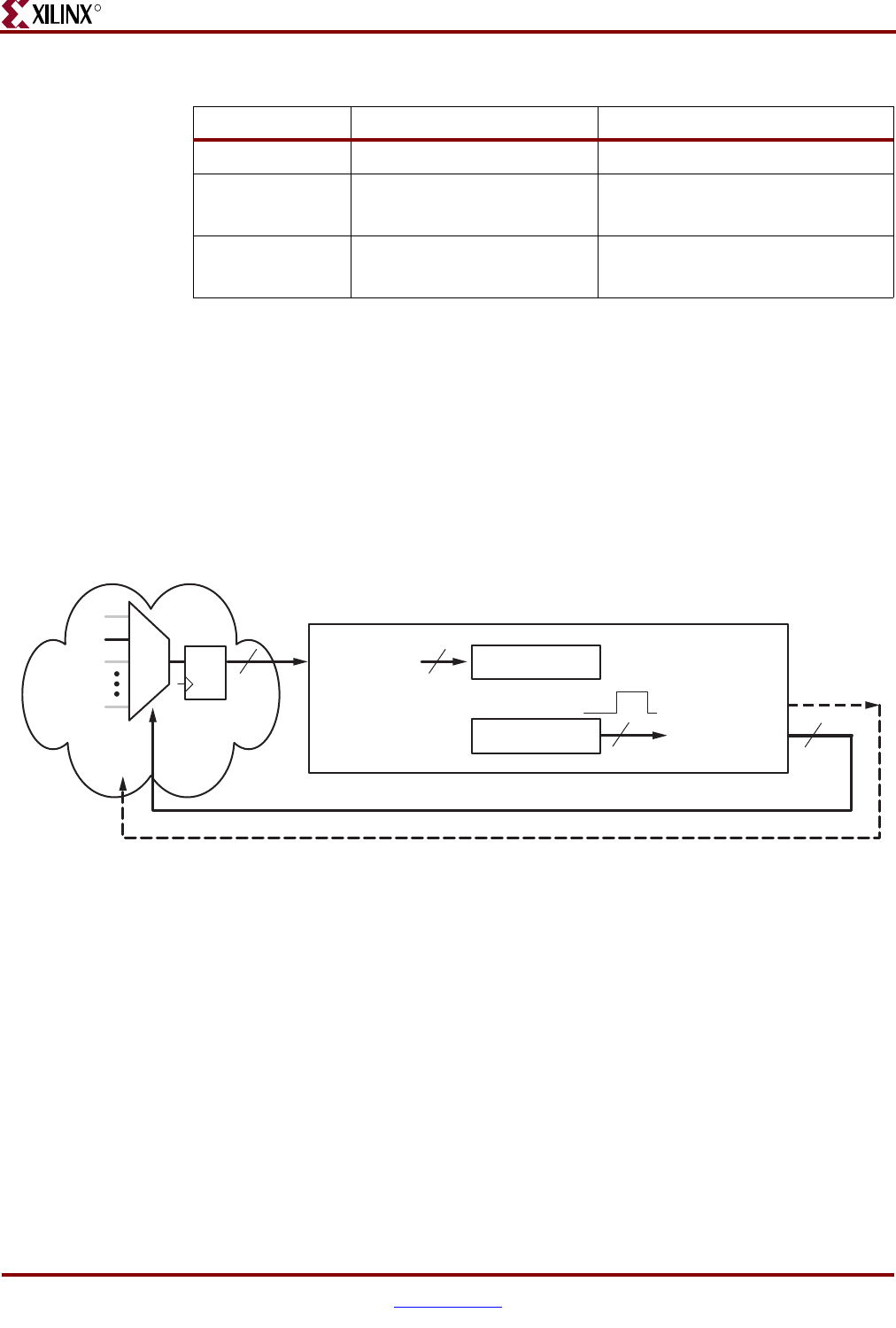
An INPUT operation transfers the data supplied on the IN_PORT input port to any one of
the 16 data registers, defined by register sX, as shown in Figure 6-1. The PORT_ID output
port, defined either by register sY or an 8-bit immediate constant, selects the desired input
source. Input sources are generally selected via a multiplexer, using a portion of the bits
from the PORT_ID output port to select a specific source. The size of the multiplexer is
proportional to the number of possible input sources, which has direct implications on
performance.
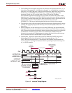
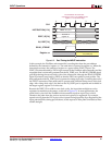
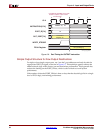
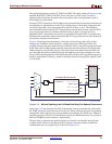
The INPUT operation asserts the associated READ_STROBE output pulse on the second
cycle of the two-cycle INPUT cycle, as shown in Figure 6-2. The READ_STROBE signal is
seldom used in applications but it indicates that the PicoBlaze microcontroller has
acquired the data. READ_STROBE is critical when reading data from a FIFO,
acknowledging receipt of data as shown in Figure 6-4.
Table 6-1: Decoding PORT_ID Depending on Number of Ports
Number of Ports INPUT OUTPUT
0 to 1 No multiplexing required No decoding required
2 to 8 Single input multiplexer
Binary encode PORT_ID
“One hot” encode PORT_ID
9 to 256 Cascaded multiplexer tree
Binary encode PORT_ID
Binary encode PORT_ID
Hybrid “one hot”/binary encoded
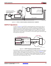
Figure 6-1: INPUT Operation and FPGA Interface Logic
n
READ_STROBE
PORT_ID[7:0]
8
Register sY or
Literal kk
Register sX IN_PORT[7:0]
8
FPGA Logic
DQ
m
PicoBlaze Microcontroller
UG129_c6_01_052004