


84 www.xilinx.com PicoBlaze 8-bit Embedded Microcontroller
UG129 (v1.1.2) June 24, 2008
Chapter 12: Simulating PicoBlaze Code
R
Using the pBlazIDE Instruction Set Simulator with KCPSM3 Programs
The pBlazIDE software primarily supports only a VHDL design flow, which is sufficient
for many applications. The KCPSM3 assembler supports Verilog, black box, and Xilinx
System Generator design flows in addition to the VHDL flow.
Fortunately, pBlazIDE has an import function that translates a KCPSM3-syntax program
into the pBlazIDE syntax. Consequently, it is possible to use the pBlazIDE instruction set
simulator to simulate KCPSM3 programs.
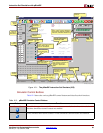
Simulating FPGA Interaction with the pBlazIDE Instruction Set Simulator
Although pBlazIDE does not simulate FPGA logic, it does provide basic capabilities to test
the PicoBlaze INPUT and OUTPUT operations that connect to FPGA logic. The DSIN,
DSOUT, and DSIO directives declare input and output ports, and also provide simple file
I/O functions. A stimulus file associated with a DSIN statement simulates data reads
during a PicoBlaze INPUT operation. Similarly, the DSOUT statement specifies an output
file where PicoBlaze OUTPUT operations are recorded.
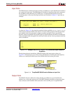
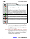
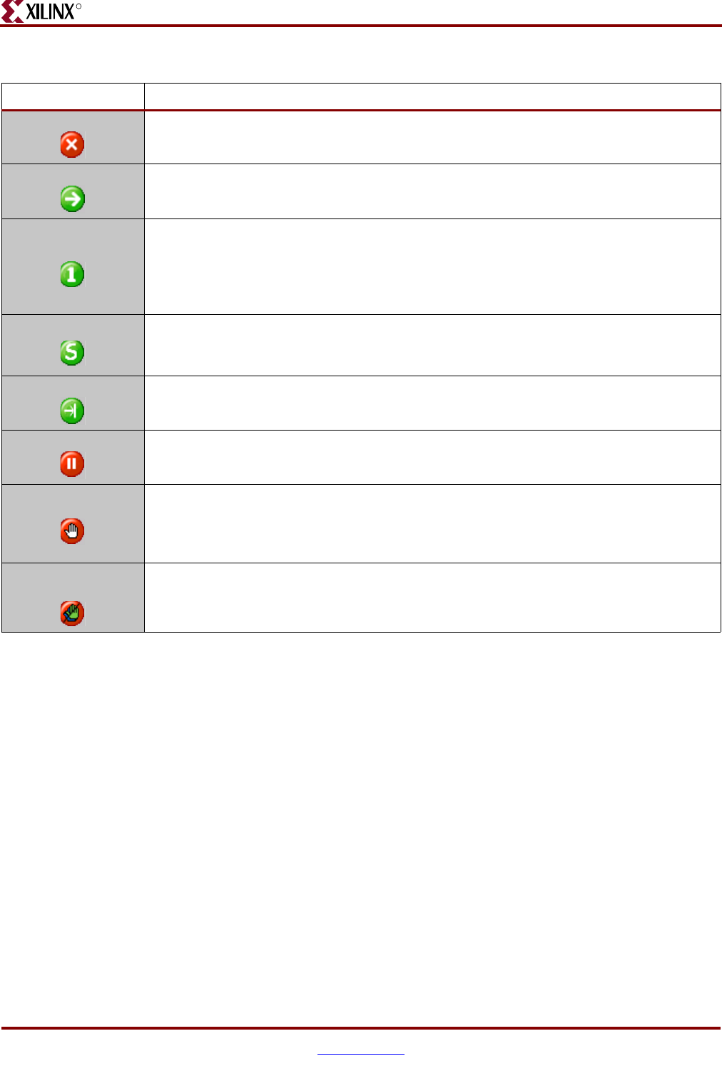
Reset Reset the simulator. Reset the Program Counter (PC) and Stack Pointer (SP). Register and
RAM values are not reset.
Run Run the program. The program continues running until an active breakpoint is
encountered or if the Reset or Pause button is pressed.
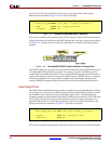
Single Step
Execute a single instruction. The active register, memory, and I/O displays are updated
and the cursor arrow advances to the next instruction. The next instruction to be executed
is highlighted in blue and a blue arrow appears to the left of the instruction line. After
executing an instruction, the code coverage indicator changes from blue to green. If
executing a valid CALL instruction, the program steps into the subroutine function.
Step Over
Behaves like the Single Step button except that the simulator does not step into CALL
instructions. If executing a valid CALL instruction, the program executes the entire
subroutine and the display advances to the instruction following the CALL instruction.
Run to Cursor Run the program until the program advances to the current cursor location.
Pause Pause a running simulation and display the current state of the PicoBlaze microcontroller.
Continue the simulation using any of the green action buttons.
Toggle Breakpoint
Set or remove a breakpoint on the instruction at the current cursor location. The instruction
line is highlighted in red and a breakpoint indicator appears to the left of the line. Multiple
breakpoints may be simultaneously active. If the simulation reaches an instruction with an
active breakpoint, the simulation automatically pauses.
Remove All
Breakpoints
Clear all active breakpoints.
Table 12-2: pBlazIDE Simulator Control Buttons (Continued)
Button Function