46 www.xilinx.com PicoBlaze 8-bit Embedded Microcontroller
UG129 (v1.1.2) June 24, 2008
Chapter 5: Scratchpad RAM
Implementing a Look-Up Table
The next few examples demonstrate both the flexibility of the scratchpad RAM and
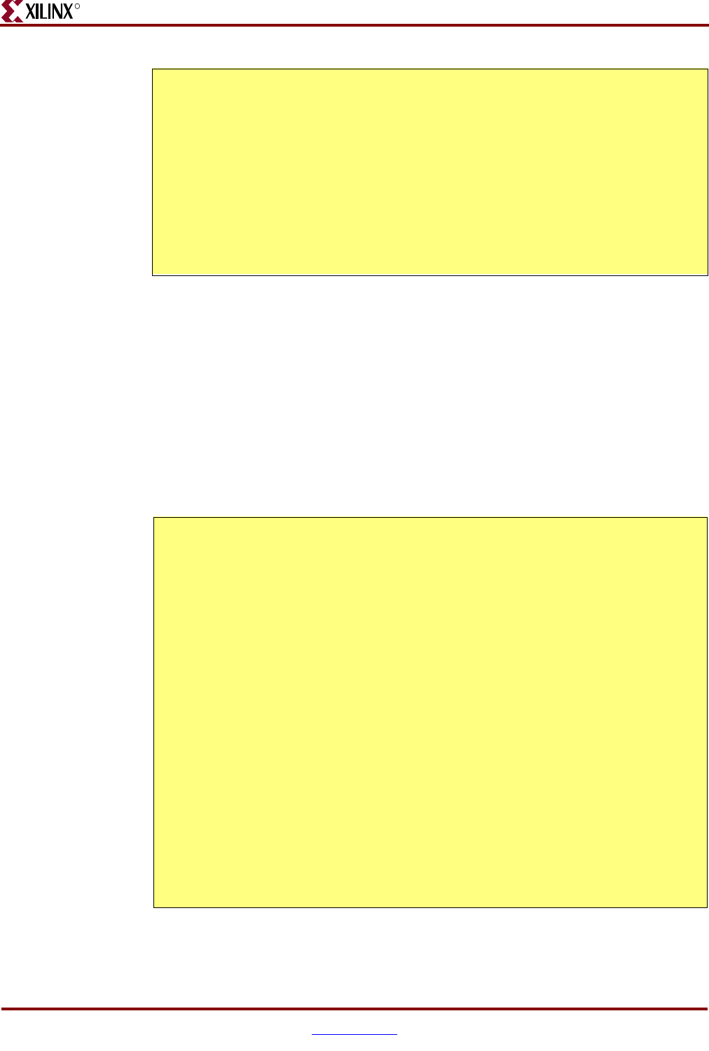
indirect addressing. The example code in Figure 5-3 uses Scratchpad RAM as a look-up
table (LUT) to convert four binary inputs to the equivalent hexadecimal character display
on a 7-segment LED. The code reads four external switches, resulting in a binary value
between 0000 and 1111. The PicoBlaze microcontroller converts each four-bit switch value
into the equivalent hexadecimal character as displayed on a 7-segment LED. The
scratchpad RAM holds the LED output patterns in the first 16 locations. The input switch
value is the address input to the RAM.
Figure 5-2: Indirect Addressing Initializes All of RAM with a Simple Subroutine
NAMEREG s0, ram_data
NAMEREG s1, ram_address
CONSTANT ram_locations, 40 ; there are 64 locations
CONSTANT initial_value, 00 ; initialize to zero
LOAD ram_data, initial_value ; load initial value
LOAD ram_address, ram_locations ; fill from top to bottom
ram_fill: SUB ram_address, 01 ; decrement address
STORE ram_data, (ram_address) ; initialize location
JUMP NZ, ram_fill ; if not address 0, goto
; ram_fill
Figure 5-3: Using Scratchpad RAM as a Look-Up Table
CONSTANT switches, 00 ; read switch values at port 0
CONSTANT LEDs, 01 ; write 7-seg LED at port 1
; Define 7-segment LED pattern {dp,g,f,e,d,c,b,a}
CONSTANT LED_0, C0 ; display '0' on 7-segment display
CONSTANT LED_1, F9 ; display '1' on 7-segment display
;
CONSTANT LED_F, 8E ; display 'F' on 7-segment display
NAMEREG s0, switch_value ; read switches into register s0
NAMEREG s1, LED_output ; load LED output data in register s1
; Load 7-segment LED patterns into scratchpad RAM
LOAD LED_output, LED_0 ; grab LED pattern for switches = 0000
STORE LED_output, 00 ; store in RAM[0]
LOAD LED_output, LED_1 ; grab LED pattern for switches = 0001
STORE LED_output, 01 ; store in RAM[1]
;
LOAD LED_output, LED_F ; grab LED pattern for switches = 1111
STORE LED_output, 0F ; store in RAM[F]
; Read switch values and display value on 7-segment LED
loop: INPUT switch_value, switches ; read value on switches
AND switch_value, F0 ; mask upper bits to guarantee < 15
FETCH LED_output, (switch_value) ; look up LED pattern in RAM
OUTPUT LED_output, LEDs ; display switch value on 7-segment LED
JUMP loop


