


PicoBlaze 8-bit Embedded Microcontroller www.xilinx.com 63
UG129 (v1.1.2) June 24, 2008
R
Chapter 8
Performance
Input Clock Frequency
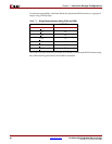
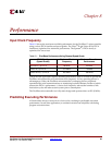
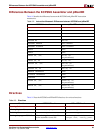
Table 8-1 shows the maximum available performance for the PicoBlaze™ microcontroller
using various FPGA families and speed grades. The Virtex
®
-II and Virtex-II Pro FPGA
families are optimized for maximum performance. The Spartan
®
-3 FPGA family is
optimized for lowest cost.
Unless the end application requires absolute performance, there is no need to operate the
PicoBlaze microcontroller at its maximum clock frequency. In fact, operating slower is
advantageous. Often, the PicoBlaze microcontroller is managing slower peripheral
operations like serial communications or monitoring keyboard buttons, neither of which
stresses the FPGA’s performance. A lower clock frequency reduces the number of idle
instruction cycles and reduces total system power consumption.
The PicoBlaze microcontroller is a fully static design and operates down to DC (0 MHz).
Predicting Executing Performance
All instructions always execute in two clock cycles, resulting in predictable execution
performance. In real-time applications, a constant execution rate simplifies calculating
program execution times.
Table 8-1: PicoBlaze Performance Using Slowest Speed Grade
FPGA Family
(Speed Grade)
Maximum Clock
Frequency
Maximum Execution
Performance
Spartan-3 (-4) FPGA 88 MHz 44 MIPS
Virtex-II (-6) FPGA 152 MHz 76 MIPS
Virtex-II Pro (-7) FPGA 200 MHz 100 MIPS