


72 www.xilinx.com PicoBlaze 8-bit Embedded Microcontroller
UG129 (v1.1.2) June 24, 2008
Chapter 10: Using the PicoBlaze Microcontroller in an FPGA Design
R
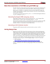
Connecting the Program ROM
The PicoBlaze program ROM is used within a VHDL design flow. The PicoBlaze assembler
generates a VHDL file in which a block RAM and its initial contents are defined. This
VHDL file can be used for both logic synthesis and simulation of the processor.
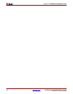
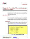
Figure 10-3 shows the component declaration for the program ROM, and Figure 10-4
shows the component instantiation. The name of the program ROM, shown as "prog_rom"
in the following figures, is derived from the name of the PicoBlaze assembler source file.
For example, if the assembler source file is named phone.psm, then the assembler
generates a program ROM definition file called phone.vhd.
To speed development, a VHDL file called embedded_KCPSM3.vhd is provided. In this
file, the PicoBlaze macro is connected to its associated block RAM program ROM. This
entire module can be embedded in the design application, or simply used to cut and paste
the component declaration and instantiation information into the user’s design files.
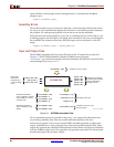
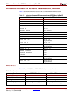
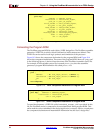
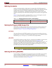
Figure 10-2: VHDL Component Instantiation of the KCPSM3
processor: kcpsm3
port map(
address => address_signal,
instruction => instruction_signal,
port_id => port_id_signal,
write_strobe => write_strobe_signal,
out_port => out_port_signal,
read_strobe => read_strobe_signal,
in_port => in_port_signal,
interrupt => interrupt_signal,
interrupt_ack => interrupt_ack_signal,
reset => reset_signal,
clk => clk_signal
);
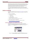
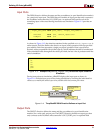
Figure 10-3: VHDL Component Declaration of Program ROM
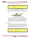
Figure 10-4: VHDL Component Instantiation of Program ROM
component prog_rom
port (
address : in std_logic_vector( 9 downto 0);
instruction : out std_logic_vector(17 downto 0);
clk : in std_logic
);
end component;
program: prog_rom
port map( address => address_signal,
instruction => instruction_signal,
clk => clk_signal
);