


PicoBlaze 8-bit Embedded Microcontroller www.xilinx.com 71
UG129 (v1.1.2) June 24, 2008
R
Chapter 10
Using the PicoBlaze Microcontroller in
an FPGA Design
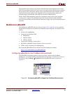
The PicoBlaze™ microcontroller is primarily designed for use in a VHDL design flow.
However, both Verilog and black box instantiation are also supported, as described below.
Similarly, Xilinx XST/ISE
®
6.2i and later versions support mixed language support where
both VHDL and Verilog can be mixed in a single project. There is also support for the Xilinx
System Generator design environment.
VHDL Design Flow
The PicoBlaze microcontroller is supplied as a VHDL source file, called KCPSM3.vhd,
which is optimized for efficient and predictable implementation in a Spartan
®
-3, Virtex
®
-
II, or Virtex-II Pro FPGA. The code is suitable for both synthesis and simulation and was
developed and tested using the Xilinx Synthesis Tool (XST) for logic synthesis and
ModelSim for simulation. Designers have also successfully used other logic synthesis and
simulation tools. The VHDL source code must not be modified in any way.
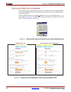
KCPSM3 Module
The KCPSM3 module contains the PicoBlaze ALU, register file, scratchpad, RAM, etc. The
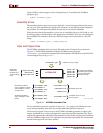
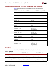
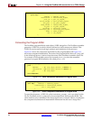
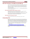
only function not included is the instruction store. The component declaration for the
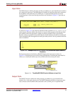
KCPSM3 module appears in Figure 10-1. Figure 10-2 lists the KCPSM3 component
instantiation.
Figure 10-1: VHDL Component Declaration of KCPSM3
component KCPSM3
port (
address : out std_logic_vector( 9 downto 0);
instruction : in std_logic_vector(17 downto 0);
port_id : out std_logic_vector( 7 downto 0);
write_strobe : out std_logic;
out_port : out std_logic_vector( 7 downto 0);
read_strobe : out std_logic;
in_port : in std_logic_vector( 7 downto 0);
interrupt : in std_logic;
interrupt_ack : out std_logic;
reset : in std_logic;
clk : in std_logic
);
end component;