


44 www.xilinx.com PicoBlaze 8-bit Embedded Microcontroller
UG129 (v1.1.2) June 24, 2008
Chapter 4: Interrupts
R
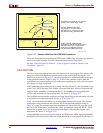
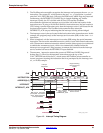
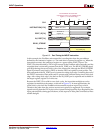
Figure 4-3 shows the same interrupt procedure but as a timing diagram. With the interrupt
enabled, the INTERRUPT input is recognized at Step (2), the same clock cycle where the
ADDRESS bus changes value. The address for the instruction ADD s0,s1 appears on the
ADDRESS bus and is pushed onto the CALL/RETURN stack. Simultaneously, the
interrupt is disabled and the ZERO and CARRY flags are preserved. The ADD s0, s1
instruction is preempted and does not yet execute. Instead, the PicoBlaze microcontroller
performs a call to the interrupt vector at location 0x3FF.
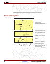
An interrupt is undesirable in timing-critical procedures or when predictable timing is a
must. Temporarily disable the INTERRUPT input using the DISABLE INTERRUPT
instruction, as demonstrated in the critical_timing subroutine in Figure 4-2. Once the
critical procedure completes, re-enable the INTERRUPT input with the ENABLE
INTERRUPT instruction.