


PicoBlaze 8-bit Embedded Microcontroller www.xilinx.com 83
UG129 (v1.1.2) June 24, 2008
Instruction Set Simulation with pBlazIDE
R
Simulator Control Buttons
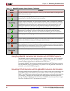
Table 12-2 shows the various pBlazIDE control buttons and describes their functions.
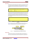
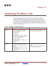
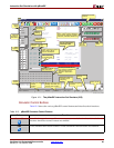
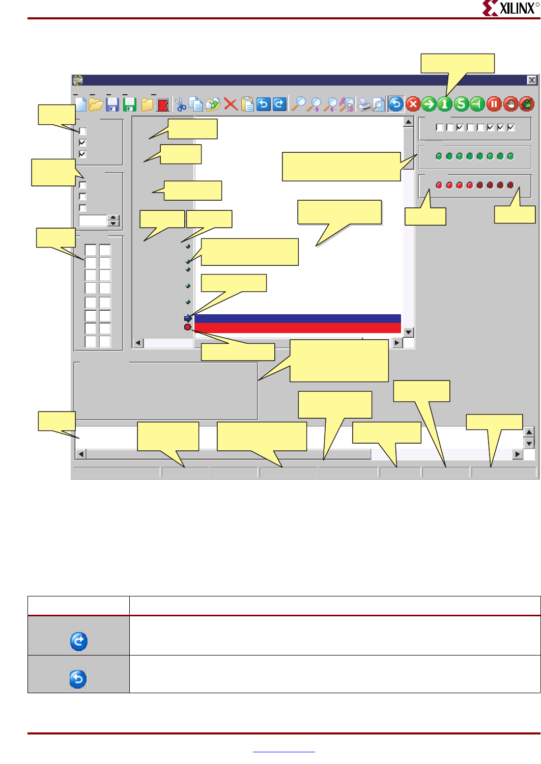
Figure 12-1: The pBlazIDE Instruction Set Simulator (ISS)
pBlaze IDE
File Edit View Settings Help
Status
Zero
Carry
Enable
Interrupt
Steady
Edge
Timer
50
Registers
00 8
00
9
000
00
1
00
A
00 B
00
2
273
00
C
00 D
F0
4
005
00
E
00
F
00
6
00
7
$00
$10
$20
$30
00 00 00 00
00 00 00 00
00 00 00 00
00 00 00 00
00 00 00 00
00 00 00 00
00 00 00 00
00 00 00 00
00 00 00 00
00 00 00 00
00 00 00 00
00 00 00 00
00 00 00 00
00 00 00 00
00 00 00 00
00 00 00 00
0123456789ABCDEF
Scratchpad RAM
$00
76543210
$27
switches
$02
76543210
$F0
mailbox
$00
$01
$02
s3
s4
$80
$000
$000 $3C001
$001 $04300
$002 $14380
$003 $31806
$004 $2C401
$005 $34001
$006 $04402
$007 $2C401
Assembler Phase 3: building simulation objects
Program is Reset
Mode: PicoBlaze-3 26: 1 Modified Instructions: 4 Time: 95 ns PC: $006
switches
DSIN
0
LEDs
DSOUT
1
mailbox
DSIO
2
input_value
EQU
s3
LED_output
EQU
s4
threshold_value
EQU
$80
ORG
0
start :
EINT ; enable interrup
poll_loop :
IN input_value , swit
COMP input_value , thre
CALL C, process_input
OUT LED_output , LEDs
JUMP poll_loop
process_input : IN LED_output , mailb
OUT LED_output , LEDs
SP: 1 ($01) Stack: $04
Simulation control
buttons
Status
flags
Constant
declaration
Data
registers
Scratchpad RAM display
only appears if STORE or
FETCH instructions
appear in application
code
Status
window
Register
aliasing
Defined start
address
Instruction
address
Interrupt
control for
simulation
Instruction
code
Code coverage indicator.
Also, click to set or
remove breakpoint
Next instruction
to be executed
Breakpoint set at
this instruction
Input, output, and I/O displays
and controls defined by DSIN,
DSOUT, and DSIO directives
Cursor row and
column
position
Number of instructions
already executed up to
current code position
Execution time at
specified clock
frequency
Current Program
Counter
Current Stack
Pointer
Stack values
Syntax-highlighted
assembly code
$01
76543210
$A5
LEDs
Port ID
Number
Port
Value
UG129_c12_01_051604
Table 12-2: pBlazIDE Simulator Control Buttons
Button Function
Assemble Assemble the open document. If no errors are encountered, the simulator is invoked and
the other simulation control buttons are enabled.
Edit Leave simulator and return to editor. All the simulation control buttons are disabled.