18 www.xilinx.com PicoBlaze 8-bit Embedded Microcontroller
UG129 (v1.1.2) June 24, 2008
Chapter 2: PicoBlaze Interface Signals
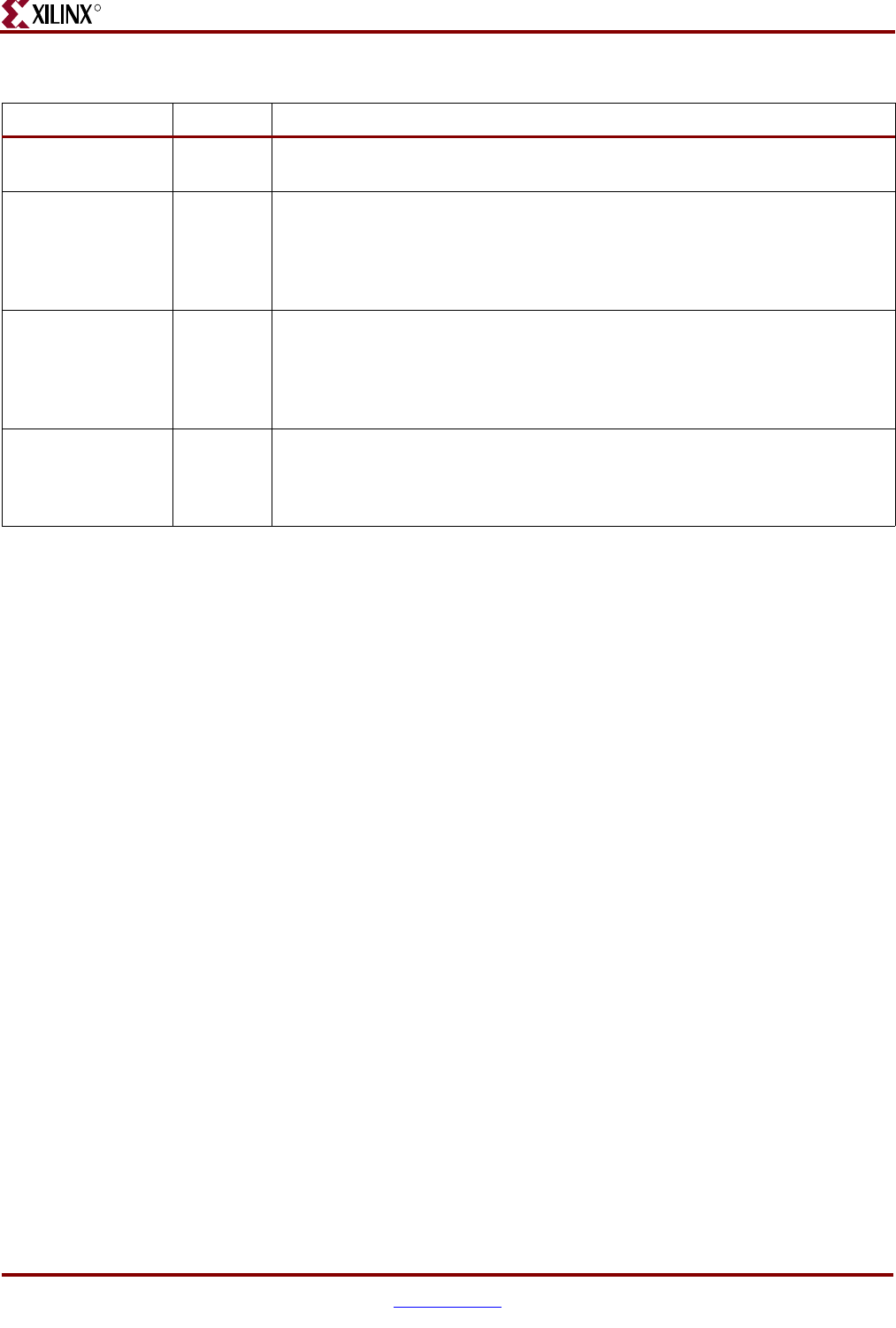
PORT_ID[7:0] Output Port Address: The I/O port address appears on this port for two CLK cycles
during an INPUT or OUTPUT instruction.
READ_STROBE Output Read Strobe: When asserted High, this signal indicates that input data on the
IN_PORT[7:0] port was captured to the specified data register during an
INPUT instruction. This signal is asserted on the second CLK cycle of the two-
cycle INPUT instruction. This signal is typically used to acknowledge read
operations from FIFOs.
WRITE_STROBE Output Write Strobe: When asserted High, this signal validates the output data on the
OUT_PORT[7:0] port during an OUTPUT instruction. This signal is asserted
on the second CLK cycle of the two-cycle OUTPUT instruction. Capture
output data within the FPGA on the rising CLK edge when WRITE_STROBE
is High.
INTERRUPT_ACK Output Interrupt Acknowledge: When asserted High, this signal acknowledges that
an INTERRUPT Event occurred. This signal is asserted during the second CLK
cycle of the two-cycle INTERRUPT Event. This signal is optionally used to
clear the source of the INTERRUPT input.
Table 2-1: PicoBlaze Interface Signal Descriptions (Continued)
Signal Direction Description


