


54 www.xilinx.com PicoBlaze 8-bit Embedded Microcontroller
UG129 (v1.1.2) June 24, 2008
Chapter 6: Input and Output Ports
R
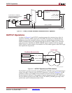
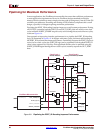
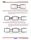
Simple Output Structure for Few Output Destinations
For eight or less simple output ports, use “one-hot” port addresses and only decode the
appropriate PORT_ID signal, as shown in Figure 6-7. This technique greatly reduces the
address decode logic which lowers cost and maximizes performance. This approach also
reduces the loading on the PORT_ID bus, which is often critical to overall system
performance.
If the number of decoded PORT_ID bits is three or less, then the decode logic fits in a single
level of FPGA logic, maximizing performance.
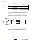
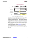
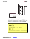
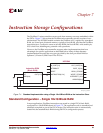
Figure 6-6: Port Timing for OUTPUT Instruction
Use WRITE_STROBE as the clock
enable to capture output values
in FPGA logic.
OUTPUT s0, 65
CLK
PORT_ID[7:0]
OUT_PORT[7:0]
WRITE_STROBE
INSTRUCTION[17:0]
FPGA Register
Captured Value from
OUT_PORT[7:0]
65
Contents of
Register s0
UG129_c6_06_060404
0
123
4