


26 www.xilinx.com PicoBlaze 8-bit Embedded Microcontroller
UG129 (v1.1.2) June 24, 2008
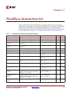
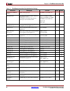
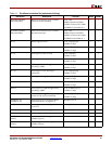
Chapter 3: PicoBlaze Instruction Set
R
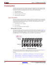
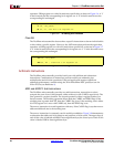
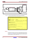
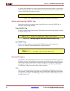
operation. ORing register sX with a bit mask sets specific bits, as shown in Figure 3-6. A ‘1’
in the bit mask sets the corresponding bit in register sX. A ‘0’ in the bit mask leaves the
corresponding bit unchanged.
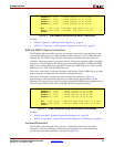
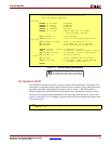
Clear Bit
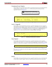
The PicoBlaze microcontroller does not have a specific instruction to clear an individual bit
or bits within a specific register. However, the AND instruction performs the equivalent
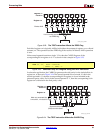
operation. ANDing register sX with a bit mask clears specific bits, as shown in Figure 3-7.
A ‘0’ in the bit mask clears the corresponding bit in register sX. A ‘1’ in the bit mask leaves
the corresponding bit unchanged.
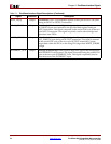
Arithmetic Instructions
The PicoBlaze microcontroller provides basic byte-wide addition and subtraction
instructions. Combinations of instructions perform multi-byte arithmetic plus
multiplication and division operations. If the end application requires significant
arithmetic performance, consider using the 32-bit MicroBlaze RISC processor core for
Xilinx FPGAs (see Reference 4).
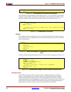
ADD and ADDCY Add Instructions
The PicoBlaze microcontroller provides two add instructions, ADD and ADDCY, that
compute the sum of two 8-bit operands, either without or with CARRY, respectively. The
first operand is a register location. The second operand is either a register location or a
literal constant. The resulting operation affects both the CARRY and ZERO flags. If the
resulting sum is greater than 255, then the CARRY flag is set. If the resulting sum is either
0 or 256 (register sX is zero with CARRY set), then the ZERO flag is set.
The ADDCY instruction is an add operation with carry. If the CARRY flag is set, then ADDCY
adds an additional one to the resulting sum.
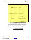
The ADDCY instruction is commonly used in multi-byte addition. Figure 3-8 demonstrates
a subroutine that adds two 16-bit integers and produces a 16-bit result. The upper byte of
each 16-bit value is labeled as MSB for most-significant byte; the lower byte of each 16-bit
value is labeled LSB for least-significant byte.
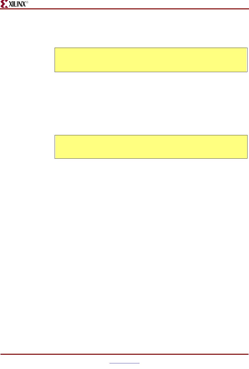
Figure 3-6: 16-Setting a Bit Location
set_bit:
; OR sX, <bit_mask>
OR s0, 01 ; set bit 0 of register s0
Figure 3-7: Clearing a Bit Location
clear_bit:
; AND sX, <bit_mask>
AND s0, FE ; clear bit 0 of register s0