


Handset Using the MDW 9031/9031DCP Pocket Phone 3
MDW 9031/9031DCP Wireless Pocket Phone Installation and Use
503-801-166 Issue 3 October 1999 83
Using Wireless Test Mode
You can determine sound clarity, signal strength, and voice quality using Wireless Test Mode.
You should use Wireless Test Mode to help you locate the best place to install the radio module(s) to optimize the
performance of your MDW 9031/9031DCP Pocket Phone. Repeat the tests several times, with the radio module
positioned in a different location each time.
By performing the tests as you walk around the area in which the handset will be used, you can determine the
handset’s range and the voice quality throughout the area of coverage. To perform the tests, all you need is an
electrical outlet for the radio module and a charged battery pack in the handset. You can perform the tests
multiple times and in any order; and you can exit at any time by pressing O.
Note: Ignore anything that displays if you press 4 while in Wireless Test Mode.
These displays are for Lucent Technologies technicians’ use only.
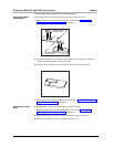
To use Wireless Test Mode:
1 Make sure the handset is turned off.
2 Press and hold the Select button ( " ) for three seconds.
3 While still holding ", press O.
The handset beeps twice, and the display shows the handset settings, indicating
you are in Local Mode. (While in Local Mode, the MDW 9031/9031DCP can still
receive notification of incoming calls.)
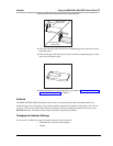
4 Press “W” (9) to enter Wireless Test Mode.
WIRELESS TEST appears on the top line of the handset display.
The handset beeps twice and, if the vibrator is enabled, it vibrates; then you hear a
simulated dial tone. This dial tone continues until you exit Wireless Test Mode.
While in this mode, the MDW 9031/9031DCP cannot make or receive calls.
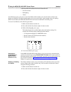
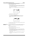
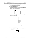
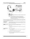
5 To identify the matching radio module for this handset, press 3.
The display indicates in which slot in the individual carrier (SLOT: n) the
matching radio module is located, using a number ( n) from 1 to 6. A stand-alone
radio module is shown as 0. For example, the display below shows a radio
module in slot 4:
ON
ON