


2 Installing the MDW 9031/9031DCP Pocket Phone Understanding Carriers
MDW 9031/9031DCP Wireless Pocket Phone Installation and Use
503-801-16622 Issue 3 October 1999
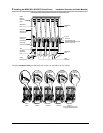
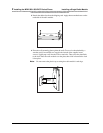
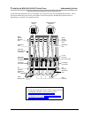
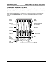
As the following illustration shows, each Model 117A3 carrier has two user-adjustable DIP switches—one in
Slot 2 that controls the power levels, and another in Slot 4 that specifies whether this particular carrier is
functioning as a control or an expansion carrier.
Go to either of the following sections:
• If you need to adjust the 117A3 carrier’s range to prevent
overlapping with other wireless products, go to
“Setting the 117A3 Carrier Power Level.”
• To skip that section, go to “Setting the 117A3 Carrier
Control/Expansion DIP Switch.”
1 2 3 4
6
4
T
RANS
T
ALK
21
O N
21
O N
5
CAUTION
U
S
E
O
N
L
Y
A
T
&
T
C
A
B
L
E
P
⁄N
8
4
7
6
6
7
8
9
6
IN
OUT
OUT OF SYNC
Rear
Exit Slots
Wall Mount
Hole
Slot
Numbers
Card Edge
Connectors
Out of Sync LED
Out Jack
In Jack
Cable
Manager Slot
Wall Mount
Hole
Slot
Numbers
Card Edge
Connectors
Power Cord
Connector
(not shown)
Wall Mount
Hole
Wall Mount
Hole
Radio
Module
Mounting
Rods
Radio
Module
Mounting
Rods
Power DIP
Switch
Control/Expansion
DIP Switch
Label with
Model Number
(not shown)
21
O N
21
O N