


Understanding Carriers Installing the MDW 9031/9031DCP Pocket Phone 2
MDW 9031/9031DCP Wireless Pocket Phone Installation and Use
503-801-166 Issue 3 October 1999 21
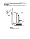
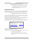
Note: The RADIO LED also may light upon installation; however, since the
RADIO LED has no significance during installation, ignore its operation.
The RADIO LED indicates a connection between the handset and the
radio module; it lights when the handset is being used as long as the
battery pack in the handset is charged.
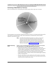
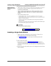
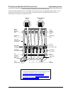
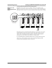
Understanding Carriers
When you install more than one radio module in a single zone, you must mount the radio modules in a carrier, so
that their signals will be synchronized. A carrier can hold up to six radio modules. The MDW 9031/9031DCP
Pocket Phone is designed to work with either of two carrier models: Model 117A3, and Model 117A4.
Note: If you currently own a Model 117A1, 117A1A, or 117A2 carrier, Lucent
Technologies will replace it with a Model 117A3 or Model 117A4 at no
charge.
If you want to install more than six radio modules, you will need more than one carrier. Systems configured as
key systems (for example, PARTNER or MERLIN) can accommodate up to 18 radio modules (three carriers);
PBX systems can accommodate up to 24 radio modules (four carriers).
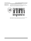
In any multiple-carrier installation, the leftmost carrier acts as the control carrier, and the remaining carriers act
as expansion carriers, passing along the synchronization signal from the control carrier. Multiple carrier
installations require that you use Model 117A3 or Model 117A4 carriers, or both.
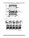
The Model 117A3 and Model 117A4 carriers are similar in general appearance, but the installation procedure for
the two models differs somewhat. A label on the left side of the carrier identifies the carrier model number.
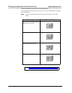
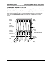
Understanding Your Model 117A3 Carrier
The installation of a Model 117A3 carrier differs in three ways from the installation of a Model 117A4 carrier:
• You may need to adjust the power DIP switch.
• You must set the Control/Expansion DIP switch.
• If you use the 117A3 as the control carrier, you must have a radio module
installed in Slot 6 of that carrier in order to pass the synchronization signal on to
the next carrier.
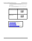
If you are installing one model of carrier, go to either of the
following sections:
• If installing a Model 117A3 carrier, go to “Understanding
Your Model 117A3 Carrier.”
• If installing a Model 117A4 carrier, go to “Understanding
Your Model 117A4 Carrier.”
If you are installing both carrier models, read both of these
sections.