


2 Installing the MDW 9031/9031DCP Pocket Phone Installing Multiple Carriers
MDW 9031/9031DCP Wireless Pocket Phone Installation and Use
503-801-16642 Issue 3 October 1999
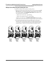
Multiple-carrier installation involves several stages:
• Mounting the carriers on the wall and cabling them.
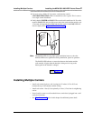
• Installing a single radio module in each carrier.
• Installing the remaining radio modules.
The most efficient method for installing carriers and their radio modules is to perform self-tests after each stage
of the installation. This enables you to spot any problems at an early stage and to avoid the necessity for
deinstalling the components in order to solve problems.
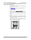
Mounting and Cabling Multiple Carriers
Perform the tests described in “Wireless Test Mode” in Chapter 3 to determine the optimal placement of the radio
module. To perform the tests, all you need is an electrical outlet for the radio module and a charged battery pack
in the handset.
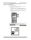
If you are installing 117A3 carriers and need to adjust the power setting to avoid interference from other wireless
products, see “Setting the 117A3 Carrier Power Level.” Also make sure you have set the Control/Expansion DIP
switch correctly (see “Setting the 117A3 Carrier Control/Expansion DIP Switch”).
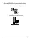
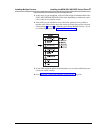
To mount and connect cable for multiple carriers:
1 Check to be sure the carrier’s power cord is unplugged from the wall outlet before
continuing.
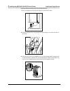
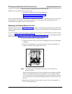
2 Choose a location backed by a wooden stud for the carrier (if unavailable, use
toggle bolts instead of the supplied wood screws).
Note: The leftmost carrier must be the control carrier; all of the others are
expansion carriers.
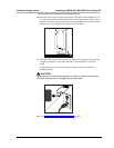
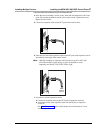
Place the carrier against the wall, leaving enough room to the right for additional
carrier(s) if applicable. Hold the carrier straight; use a level if needed. Using a
nail or pencil, mark screw locations through the four wall-mount holes. Start the
screws, leaving the screw heads protruding approximately ½ inch (12 mm) from
the wall.
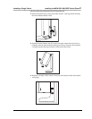
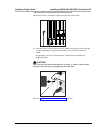
3 Repeat Steps 1 through 3 for each carrier, leaving 1 foot (0.3 m) optimally to 4
feet (1.2 m) between carriers.
1 2 3 4
6
T
RANS
T
ALK
5
C
A
U
T
I
O
N
U
S
E
O
N
L
Y
A
T
&
T
C
A
B
L
E
P
⁄
N
8
4
7
6
6
7
8
9
6
I
N
O
U
T
O
U
T
O
F
S
Y
N
C
C
O
N
T
R
O
L
/
E
X
P
A
N
S
I
O
N
M
N
N
O
E
A
P
T
R
H
A
N
H
A
P
T
E
R
G
R
R
E
P
R
A
C
I
T
E
-
O
K
L
O
R
E
M
I
P
S
U
M
R
E
P
R
A
C
I
T
E
-
O
K
R
E
P
R
A
C
I
T
E
-
O
K
X
E
R
T
F
A
M
R
U
K
L
A
R
I
E
N
L
O
R
E
P
R
A
C
I
T
E
-
O
K
L
O
R
E
M
I
P
S
U
M
X
E
R
T
F
A
M
R
U
K
L
A
R
I
E
N
L
O