


2 Installing the MDW 9031/9031DCP Pocket Phone Understanding Carriers
MDW 9031/9031DCP Wireless Pocket Phone Installation and Use
503-801-16628 Issue 3 October 1999
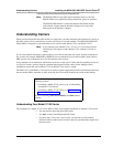
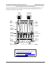
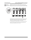
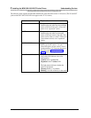
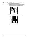
The following chart explains the label that identifies the jacks and LEDs on the 117A4 carrier. (The IN and OUT
jacks and the OUT OF SYNC LED also appear on the 117A3 carrier.)
Label Explanation
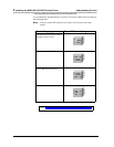
IN Designates the modular jack that accepts the
modular plug and cable from the preceding
carrier to the left. If the jack is in use, this
carrier is an “expansion” carrier.
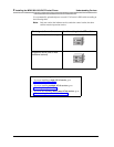
OUT Designates the modular jack that accepts a
modular plug and cable to connect this
carrier to the next carrier to the right. This
carrier can be either a “control” carrier (if it
is the leftmost carrier) or an “expansion”
carrier.
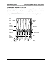
OUT OF SYNC Designates the upper of two LEDs. If the
LED is not lit, the carrier is “in sync.”
If the LED glows red, the carrier is out of
synchronization. Call Customer Support as
described in the Copyright and Legal
Notices at the beginning of this book.
CONTROL/EXPANSION Designates the lower of two LEDs. The
color of the LED indicates the carrier
configuration:
Control carrier = green LED
Expansion carrier = amber LED
The light pattern indicates whether the
carrier is operational:
Glowing steadily = no problem
Blinking = no radio module(s) in the carrier