


2 Installing the MDW 9031/9031DCP Pocket Phone Installation Overview for Radio Modules
MDW 9031/9031DCP Wireless Pocket Phone Installation and Use
503-801-16612 Issue 3 October 1999
Installation Overview for Radio Modules and Carriers
This section explains how to install radio modules and carriers. You should proceed through this section in the
following order:
1 “Radio Module/Switch Wiring”
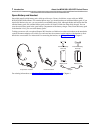
2 “Key Components”
3 “Positioning a Radio Module or Carrier(s)”
4 “Using Wireless Test Mode” (in Chapter 3)
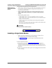
5 Choose one of the following paths, depending upon which components you are
installing:
~ If you are installing a single radio module, go to “Installing a Single Radio
Module.”
~ If you are installing one or more carriers (from two to 24 radio modules), go
to “Understanding Carriers.”
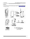
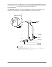
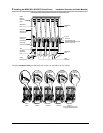
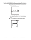
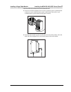
Note: The illustrations in this chapter depict PARTNER System hardware; your
hardware may differ from these illustrations.
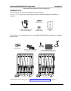
Radio Module/Switch Wiring
If your installation requires customized wiring, the wiring technician should match the Pin numbers with the
switch interfaces as follows:
Switch Interface Pin #
ATL (MERLIN, DEFINITY) 1, 2
ETR (PARTNER) 3, 6
T/R (Tip/Ring) 5, 4