


6-12 INSTALLING INTEL TELEPHONY COMPONENTS
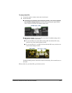
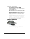
Connecting MSI/x analog station boards
1. If the MS/x board is an ISA board: Use the 50-pin RJ-21X cable to connect the board
to the port on the BCP connection panel port labeled
MSI Board.
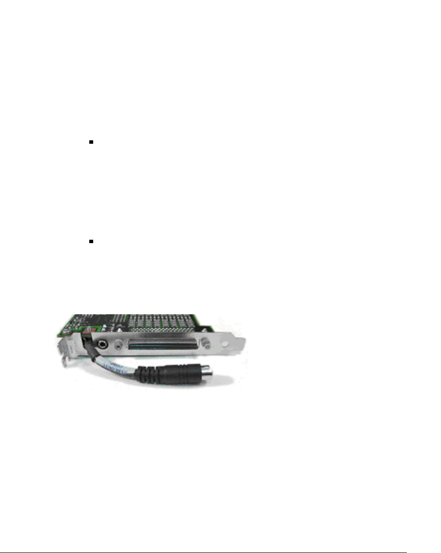
If the MS/x board is a PCI board: Attach the 50-pin RJ-21X cable to the port on the
BCP connection panel port labeled
MSI Board. Use the 37-pin D-shell adapter cable
to connect the board to the RJ-21X cable.
Note:
To avoid damaging the MSI/x board, do not plug trunk lines from the telephone
company into Station Line jacks S1-S24 on the BCP connection panel.
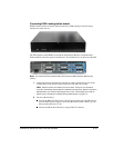
2. Connect your phones:
If you are setting up an analog system: Using RJ-11 phone cables, connect your
analog phones to the jacks labeled
Station Lines on the BCP connection panel. Use
jacks S1-S8 for 8-station boards, S1-S16 for 16-station boards, or S1-S24 for
24-station boards.
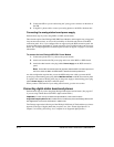
Assign your Operator to station S1 and other people who can handle a large volume
of calls to stations S2-S4. If the TeleVantage Server goes into failover, your first 4
analog trunks (T1-T4) will be routed directly to stations S1-S4. See “Failover
support” in Chapter 2 in Installing TeleVantage for more information.
If you are setting up a T1, E1, or Internet telephony system: Using RJ-11 phone
cables, connect your analog phones directly to the MSI/x board.
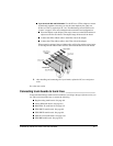
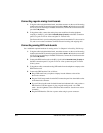
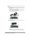
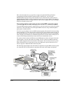
Connecting DISIx analog station boards
DISIx boards are connected to stations via an external Intel Dialogic DISIx station breakout box,
not via a BCP connection panel.
1. Connect the board to the station breakout box using a 68-pin SCSI-3 cable.
2. Using RJ-11 phone cables, connect your analog phones to the breakout box.