


6-6 INSTALLING INTEL TELEPHONY COMPONENTS
Installing Intel Dialogic boards ______________________________
Important: Shut down the TeleVantage Server PC, switch off the power, and unplug the power
cords before opening the PC cover, to avoid the risk of electric shock.
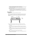
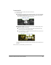
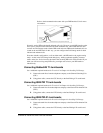
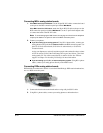
1. For each board, insert the board’s edge connector into the bus slot. The boards fit
tightly. Insert the front portion of the board first. The notch on the other end allows the
board to be tipped forward, making insertion easier.
Apply pressure only to the top edge of the board, and gently rock the board forward
and backward to seat the edge connector into the slot.
2.
If you are using Internet telephony boards: Install a third-party Network Interface
Card (NIC) in the TeleVantage Server PC, and connect it to your network, if you have
not already done so. Refer to the documentation that came with your NIC for
instructions.
Note:
Even if your DM/IPx board contains a built-in NIC, you must install a third-party
NIC and connect it to your network.
3. If you are using Toshiba Strata CS-DKTU digital station boards: Insert the board
into an available 5V PCI slot.
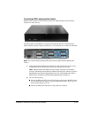
4. Connect ISA or PCI boards with the appropriate ribbon cable. Be sure to adhere to the
following guidelines when connecting boards with ribbon cables:
If you have more connectors than boards, be sure to use both end connectors,
leaving the unused connectors in the middle of the ribbon cable. This is especially
important with the CTbus ribbon cable, since it runs at a higher frequency and is
more prone to termination or antenna effects.
Make sure that there is no more than 7 inches of unconnected cable (5 unused
connectors on a standard Intel Dialogic H.100 cable) between any two adjacent
boards. If necessary, rearrange the boards in your system or use a cable with fewer
connectors.
Tuck the cable down so that unused connectors do not get in the way when you
replace the PC cover.
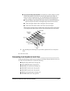
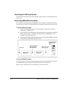
If you have ISA boards: Attach the end connector of the SCbus ribbon cable to the
SCbus connector on the top edge of the first board. Match up the notches on the
connectors for proper insertion—there is only one way that the connector fits.
Attach the ribbon cable to the SCbus connector on the next board until all ISA
boards are connected by the cable.
If you have PCI boards: Attach the end connector of the CTbus ribbon cable to the
CTbus connector on the top edge of the first board. Match up the notches on the
connectors for proper insertion—there is only one way that the connector fits.
Attach the ribbon cable to the CTbus connector on the next board until all PCI
boards are connected by the cable.