


Vmux-2100 Installation and Operation Manual Chapter 7 Monitoring and Statistics Collection
Alarms 7-3
Working with Permanent Buffer
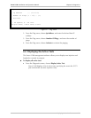
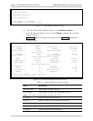
The permanent buffer is represented by the Alarm Status screen.
To access the Alarm Status screen:
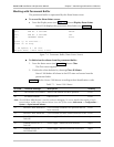
• From the Display menu (see Figure 7-2), choose Display Alarm Status.
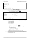
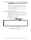
Vmux-2100 displays the permanent alarm buffer (see Figure 7-4).
(047) FAN No. 4 FAILURE MAJOR
(047) FAN No. 4 FAILURE OFF
(20) INTERNAL ERROR Event
Press ‘y’ To Continue...
Press ‘n’ To Stop.
@ - Db Update; # - Db Undo
ESC-prev.menu; !-main menu; &-exit
Figure 7-4. Permanent Buffer (Alarm Status Screen)
To delete inactive alarms from the permanent buffer:
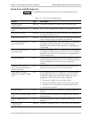
1. From the Status menu (see Figure 7-1), choose Clear.
The Clear menu appears.
2. Confirm the alarm deletion by choosing Clear all Alarms.
Vmux-2100 deletes all alarms in the OFF state and events from the
permanent buffer.
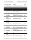
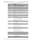
Table 7-1 lists the Vmux-2100 alarms according to their identification codes.
Table 7-1. Vmux-2100 Alarms
ID Code Terminal Message Description Severity
18 DB UPDATE OCCURRED Vmux-2100 database has been updated Event
20 INTERNAL ERROR Software error Event
Note: The INTERNAL ERROR alarm is used for software debugging. To receive detailed description of each
internal alarm, enable ‘Open Internal Alarms’ from the System menu (Main menu > Configuration >
System > Open Internal Alarms).
21 MODULE WAS REMOVED A voice module installed in the specified slot has
been removed
Event
22 MODULE WAS INSERTED A voice module has been inserted from into a slot Event
40 POWER SUPPLY No. 1
FAILURE
Power supply 1 failure has been detected Major
41 POWER SUPPLY No. 2
FAILURE
Power supply 2 failure has been detected Major
42 POWER SUPPLY NO. 1
WAS REMOVED
Power supply 1 has been removed from its slot Major