


Chapter 2 Installation and Setup Vmux-2100 Installation and Operation Manual
2-2 Installation and Setup
2.2 Package Contents
The Vmux-2100 package includes the following items:
• One Vmux-2100 unit
• Vmux-2100 installation and operation manual
• CBL-RJ45/2BNC, RJ-45 to BNC interface adapter (if ordered)
• CBL-VMUX-MM-MODEM cross cable (if ordered)
• AC power cord or DC power supply connector kit.
2.3 Installation and Setup
The Vmux-2100 unit is designed for desktop or bench installation and is delivered
as a fully assembled unit. No provisions are made for bolting the unit to a tabletop.
To install Vmux-2100:
1. Determine the required configuration of Vmux-2100, in accordance with your
application.
2. Set the E1 main link board internal jumpers to match E1 connection type:
balanced or unbalanced.
3. Connect the E1/T1 voice port.
4. Connect the 10/100BaseT or E1/T1 main link.
5. Connect an ASCII terminal or a PC running a terminal emulation software.
6. Connect power to the unit.
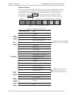
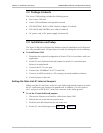
Setting the Main Link E1 Internal Jumpers
When using the E1 main link, set the E1 main link board internal jumpers to match
the E1 connection type: balanced or unbalanced. In addition, you can connect
pin 3 and pin 6 of the RJ-45 E1 main link connector to the frame ground.
To set the E1 main link board jumpers:
1. Disconnect all power and interface cables from Vmux-2100.
2. Release the two main link rear panel screws.
3. Slide the main link board interior out of the unit.
4. Set the E1 main link jumpers (see Figure 2-1 and Table 2-1).