


Chapter 5 Configuring Vmux-2100 for a Typical Application Vmux-2100 Installation and Operation Manual
5-6 Configuring Vmux-2100 for Operation with CCS Signaling
AM
5.4 Configuring Vmux-2100 for Operation with CCS
Signaling
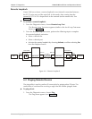
Configuration of the Vmux-2100 units operating with the CCS signaling is similar to
the configuration for operation with the CAS signaling, except for the following:
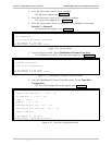
1. From E1 Parameters menu, set the framing type of the external E1 links to
G.732N (Main Menu > Configuration > Card > Slot 1 > Group 1 >
External 1 > E1 Parameters).
2. From E1 Parameters menu, set the signaling type of the external E1 links to CCS
(Main Menu > Configuration > Card > Slot 1 > Group 1 > External 1 >
E1 Parameters).
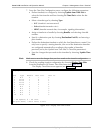
3. Display the Time Slot Configuration menu, and configure the timeslots
belonging to the external port 1 of group 1 (Main Menu > Configuration >
Card > Slot 1 > Group 1 > External 1 > Distribution Of Framer Time Slots
> Time Slot Configuration):
Update from Time Slot – 1
To Time Slot – 31
Type – Voice
Bundle – 1
Destination Port ID – 1
Destination Time Slot ID – 1.
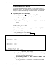
4. Once you assign all timeslots belonging to the external port 1 of group 1 to
carry voice, assign one of them (for example, timeslot 31) to carry signaling
information:
Update from Time Slot – 31
To Time Slot – 31
Type – HDLC
Bundle – 1
Destination Port ID – 1
Destination Time Slot ID – 31.
5. Update the timeslot database from the Time Slot Configuration menu.
6. Repeat step 1 to step 4 for all active external ports on all Vmux-2100 slots.
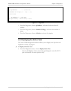
7. When working with CCS-SS7, you can instruct Vmux-2100 to drop certain
amount of fill-in signal units (FISUs) by selecting the appropriate SS7 keep-alive
suppression rate (Main Menu > Configuration > System > Management >
Signaling Configuration> SS7 Keep-Alive Suppression Rate).