


Chapter 2 Installation and Setup Vmux-2100 Installation and Operation Manual
2-4 Installation and Setup
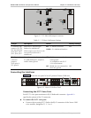
Connecting the Main Link
The Vmux-2100 Ethernet main link interface terminates in an 8-pin RJ-45
connector. Appendix A specifies the pinout of the Ethernet connector. The
Ethernet main link port supports connection via straight and cross cables.
To connect the Ethernet main link:
• Connect the LAN to the RJ-45 connector designated ETH.
The E1/T1 main link interface terminates in an 8-pin RJ-45 balanced connector.
Appendix A specifies the pinout of the E1/T1 balanced connector.
To connect the balanced E1/T1 main link:
• Connect the E1/T1 link to the RJ-45 connector designated E1 A or E1 B.
To connect the unbalanced E1 main link:
1. Insert the RJ-45 plug of the CBL-RJ45/2BNC adapter into the Vmux-2100
RJ-45 connector designated E1 A or E1 B.
2. Connect the coax cable to the BNC connectors of the CBL-RJ45/2BNC
adapter.
Connecting the ASCII Terminal
The Vmux-2100 control port terminates in a 9-pin D-type female interface
connector. Appendix A specifies the pinout of the control port connector.
To connect the ASCII terminal directly to the CONTROL port:
1. Connect the standard DB-9 flat cable to the 9-pin connector, designated
CONTROL.
2. Connect the other side of the cable to the ASCII terminal.
To connect the ASCII terminal via modem link:
1. Connect the VMUX connector of the CBL-VMUX-MM-MODEM cross cable to
the CONTROL port (see Appendix A for the cable wiring diagram).
2. Connect the MODEM connector of the cross cable to the local modem.
3. Connect the remote modem to the ASCII terminal.