


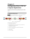

Chapter 5 Configuring Vmux-2100 for a Typical Application Vmux-2100 Installation and Operation Manual
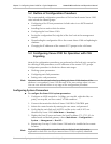
5-4 Configuring Vmux-2100 for Operation with CAS Signaling
AM
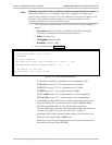
4. Display the E1 Parameters menu, and set the E1 port of group 1 to the
following values (Main Menu > Configuration > Card > Slot 1 > Group 1
> External 1 > E1 Parameters):
Connect – Yes
Frame – G.732S
Restoration – CCITT
Clock Source – Lbt
Interface Type –Dsu
Idle Code – 7E
Signaling – CAS
Profile – 1.
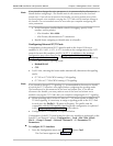
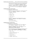
5. Display the Time Slot Configuration menu, and configure the timeslots
belonging to the external port 1 of group 1 (Main Menu > Configuration >
Card > Slot 1 > Group 1 > External 1 >
Distribution Of Framer Time Slots > Time Slot Configuration):
Update from Time Slot – 1
To Time Slot – 31
Type – Voice
Bundle – 1
Destination Port ID – 1
Destination Time Slot ID – 1.
Vmux-2100 displays timeslot 16 as ‘Not Connected’ (NC), because it carries CAS
signaling information.
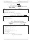
6. Update the timeslot database from the Time Slot Configuration menu.
7. Repeat step 4 to step 6 for the external port 2 of group 1, except for the
following:
Assign 2 to the Destination Port ID for the timeslots in step 5.
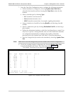
8. Display the Group 2 menu, and assign the 172.17.15.12 IP address to the
group 2 (Main Menu > Configuration > Card > Slot 1 > Group 2).
9. Repeat step 3 to step 6 for the external port 1 of group 2, except for the
following:
Assign destination IP 172.17.15.21 to the bundle 1 in step 2
Assign 3 to the Destination Port ID for the timeslots in step 5.
10. Repeat step 4 to step 6 for the external port 2 of group 2, except for the
following:
Assign 4 to the Destination Port ID for the timeslots in step 5.
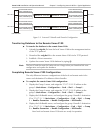
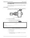
Figure 5-2 summarizes the external E1 bundle and timeslot configuration of the
local and remote units.
Note