


Vmux-2100 Installation and Operation Manual Chapter 5 Configuring Vmux-2100 for a Typical Application
AM Configuring Vmux-2100 for Operation with CAS Signaling 5-3
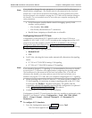
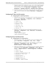
7. Display the Signal Profile Configuration menu, enter a desired signaling system
profile number (1) and configure it according to the system used by the PBX
connected to the V-4E1 card (Main Menu > Configuration > System >
Management > Signaling Configuration> Signaling Profile Configuration).
8. Display the Hub menu and enter the existing main link card (M-IPE1) and the
voice card (V-4E1) into the unit’s database (Main Menu > Configuration >
Hub).
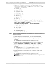
Configuring E1 Main Link Parameters
Configuring the E1 main link parameters:
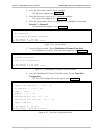
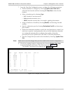
1. Display the Main Link menu, and configure the E1 main link parameters to the
following values (Main Menu > Configuration > Card > Main Board >
E1 Parameters > Main Link 1):
Connect – Yes
Frame – G.732N
Restoration – CCITT
Clock Source – Lbt
Interface Type – Dsu
Idle Code – 7E.
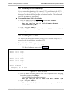
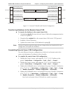
2. Display the Time Slot Table menu and assign the timeslots to carry data
(Main Menu > Configuration > Card > Main Board > E1 Parameters >
Time Slot Table):
Yes – connected (assigned)
No – disconnected (not assigned).
Configuring Voice Card Parameters
Configuring the voice card parameters:
1. Display the Group 1 menu, and assign the 172.17.15.11 IP address to the
group 1 (Main Menu > Configuration > Card > Slot 1 > Group 1).
2. Display the Bundle Configuration menu, and add bundle 1 to the system
(Main Menu > Configuration > Card > Slot 1 > Group 1 >
Bundles Parameters > Bundle Configuration).
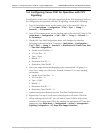
3. Display the Edit Bundle menu, and configure the group 1 bundle 1 parameters
to the following values (Main Menu > Configuration > Card > Slot 1 >
Group 1 > Bundles Parameters > Bundle Configuration > Edit Bundle):
Connect – Yes
Function – TDMoIP
Max Bytes In Multiplexed Frame – 500
Destination IP – 172.17.15.21
Destination Bundle – 1
Packetizing Interval – 30
Coder/Rate – G.723.1/6.4
Fax/Modem – Enable at 9.6 kbps.