


Front Panel Indicators 3-1
Chapter 3
Operation
This chapter provides the following information for Vmux-2100:
• Vmux-2100 front-panel indicators
• Operating procedures (turn-on, front-panel indications, performance
monitoring and turn-off).
Installation procedures given in Chapter 2 must be completed and checked before
attempting to operate Vmux-2100.
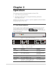
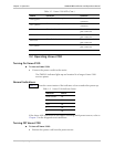
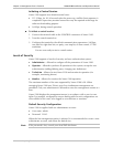
3.1 Front Panel Indicators
The front panel of Vmux-2100 includes a series of LED indicators that show the
current operating status of the unit (see Figure 3-1). Additional indicators are
located on the rear panel, as shown in Figure 3-2. Table 3-1 lists and describes the
Vmux-2100 indicators.
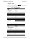
Vmux-2100
Figure 3-1. Vmux-2100, Front Panel
Vmux
2100
PS1PS2
1
LOC REM
234VC-4E11
LOC REM
234VC-4E1
1
LOC REM
POWERPOWER
234
41
32
VC-4E11
LOC REM
234VC-4E1
LOC
REM
A
ETH/E1 CONTROL
ETH
ACT LINK
TST
ALM
E1 B
Figure 3-2. Vmux-2100, Rear Panel
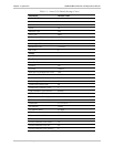
Table 3-1. Vmux-2100 LEDs
Name Function Location
TST (yellow) ON – A test is active Front panel and main
link module
ALM (red) ON – Alarm is present Front panel and main
link module
PWR1 (green) ON – Power supply 1 is ON Front panel
PWR2 (green) ON – Power supply 2 is ON Front panel
POWER ON (green) – A power supply is ON
ON (red) – A power supply is OFF
Power supply module