


Chapter 4 Management from a Terminal Vmux-2100 Installation and Operation Manual
4-24 Configuring Main Link and Voice E1/T1 Ports
266–399 Feet
399–533 Feet
533–655 Feet.
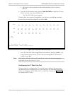
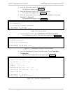
Next, the timeslots that are to carry user data are assigned by choosing Time Slot
Table From the T1 Parameters menu (as described for the E1 links)
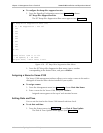
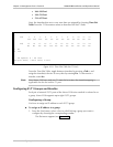
Time Slot Table
Ts# 1 2 3 4 5 6 7 8 9 10 11 12
Yes Yes Yes No No No No No No No No No
Ts# 13 14 15 16 17 18 19 20 21 22 23 24
No No No No Yes No No No No No No No
1. No
2. Yes
@ - Db Update; # - Db Undo
ESC-prev.menu; !-main menu; &-exit
Figure 4-28. Time Slot Table (for T1 Link)
From the Time Slot Table, toggle between timeslots by pressing <Tab>, and
assign the timeslot(s) that are to carry data by entering Yes. To disconnect a
timeslot, enter No.
Since Vmux-2100 uses only one T1 main link at a time, the timeslot mapping is
applicable also for the inactive T1 port.
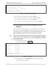
Configuring E1/T1 Groups and Bundles
Each pair of external E1/T1 ports of the Vmux-2100 voice module is referred to as
a group. Vmux-2100 supports up to eight E1/T1 groups.
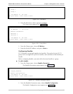
Configuring a Group
You have to assign an IP address to each E1/T1 group.
To assign an IP address to a group:
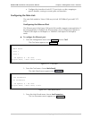
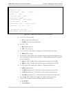
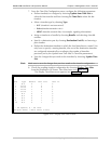
1. From the Card menu, select a slot, to which belong a group you want to
configure by choosing the corresponding number.
The Slot menu appears (see Figure 4-29).
Note