


Chapter 4 Management from a Terminal Vmux-2100 Installation and Operation Manual
4-22 Configuring Main Link and Voice E1/T1 Ports
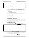
Idle Code (code transmitted to fill unused timeslots in the E1 frames):
00 to ff.
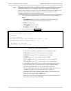
4. From the E1 Parameters menu, choose Time Slot Table to assign the E1 main
link to carry the user data (and idle code).
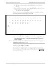
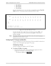
The Time Slot Table menu appears.
Timeslots that are connected (assigned to carry data) are marked Yes; timeslots
that are disconnected (not assigned) are marked No.
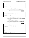
Time Slot Table
Ts# 1 2 3 4 5 6 7 8 9 10 11 12
Yes Yes Yes No No No No No No No No No
Ts# 13 14 15 16 17 18 19 20 21 22 23 24
No No No No Yes No No No No No No No
Ts# 25 26 27 28 29 30 31
No No No No No No No
1. No
2. Yes
>
@ - Db Update; # - Db Undo
ESC-prev.menu; !-main menu; &-exit
Figure 4-26. Time Slot Table (for E1 Link)
5. From the Time Slot Table, toggle between timeslots by pressing <Tab>, and
assign the timeslot(s) that are to carry data by entering Yes. To disconnect a
timeslot, enter No.
Since Vmux-2100 uses only one E1 main link at a time, the timeslot mapping is
applicable also for the inactive E1 port.
Configuring the T1 Main Link Port
The procedure for configuring the T1 main link port is similar to the procedure
described above for configuring the E1 main link port. The following parameters,
which are configured via the Main Link 1 or Main Link 2 menu (see Figure 4-27),
are unique to the T1 links:
Note